


Chally72
-
Posts
499 -
Joined
-
Last visited
-
Days Won
32
Content Type
Profiles
Forums
Downloads
Store
eMastercam Wiki
Blogs
Gallery
Events
Posts posted by Chally72
-
-
MC2024 dialog is actually slightly bigger than 2023 by default, and if you look at the tool page, it has been redesigned and expanded as well to create more room as well and get a few more rows to show tools along.
I'm on the forums discussing these items as I know that as a user, I'd have appreciated this kind of dialogue on some of the choices that affected me and my workflow, and we listen heavily to feedback in targeting enhancements and changes to make users' lives better. Thanks for the continued feedback on all aspects of the product
-
 2
2
-
-
2 hours ago, Leon82 said:
If you move you mouse and accidentally hit the wheel as you pass over it could change them inadvertently
This works the same way in all panels with drop downs and has for several years, so if you haven't run into it yet then chances are it'll be a similar experience here.
-
1
-
-
31 minutes ago, Jobnt said:
Little fissaroo for ya...
My mousewheel is smooth (i.e. it sucks) and it's difficult to get things to scroll one item at a time. Been looking for an excuse to get a new one.
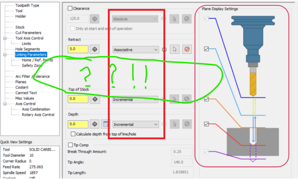
Uhh, here's some room... ??!!
There might be something called Feed plane that appears in some circumstances
.gif ";)")
-
3
-
-
There were a few areas we specifically targeted to improve the linking page for. The biggest was- how do we get Tip Comp and Breakthrough onto the same page with the rest of the linking parameters? It was a huge impediment to learning the toolpath and also to understanding what a path was doing when you had to visit not only the linking page, but also a subpage (that depending on the toolpath was either under Linking parameters or Cut parameters) to get a complete picture of what depth the hole would actually be drilled to, for example. Adding options to a page that was already full always comes with a compromise, and in this case the radiobuttons took up too much room and had to be changed to a dropdown, but we feel the visibility of the tip comp settings is the more important choice here, given how many problems it causes when you copy an op or leave it on and then drill to a wrong depth or don't understand why the path isn't giving you what you want.
When we talk about clicks, first we have to look at how often we're changing from incremental to absolute and back- almost never. It's a setting that's changed once when the path is initially made, and usually not touched after that. Tip comp, or depths, however, are things that require constant tweaking as you dial in a process, and making a user take two extra clicks and jump to a different page to even view these settings is mouse miles, too! Also, as mentioned, there is the ability to simply hover over the dropdown and scroll the mousewheel- so we went from one click to "zero" clicks from that perspective. In terms of visually digesting what a toolpath is set at, as well, I'd have to mentally spend some energy to scan through the column of radiobuttons to, say, make sure that all my settings are indeed incremental, or associative, etc, whereas it's a lot easier to "tin soldier inspect" the dropdowns and spot the one that might be set wrong or out of place.
UI changes or tweaks always come with compromises when an existing interface has been around for so long and isn't in a state where it can be easily expanded. In this case we felt that these changes offered much more value than what retaining the radiobuttons offered.
-
 3
3
-
5
-
 2
2
-
-
The override values are being incorrectly latched onto by the tool page- Slavecam has found this at about the same time as us. This is R-32638, and we're examining options to fix this in 2024 currently.
-
1
-
2
-
-
Can you send me a file, please? [email protected].
-
Those Makinos like lots of points. If you have any tilt at all, consider dropping your Max Angle Step on the TAC page from 3 degrees to 0.1-0.5 degrees.
-
1
-
2
-
-
I'd suspect you've probably nailed what is happening here. Toolpath transform by Geometry just doesn't support what Model Chamfer needs to successfully calculate.
-
Transforming by Geometry has the potential to create issues including circular dependencies, because you're transforming the geometry, then reapplying/recalculating the toolpath from scratch on the transformed geometry. So, it may recalculate against things like stock that are in the original location, but the geometry has shifted to a new location, etc etc as an example. Transforming by NCI is simply applying a transformation to the point cloud that is the calculated toolpath, and is fairly bulletproof. Unless you have a specific reason to transform by geometry, stick with NCI transform.
-
2
-
-
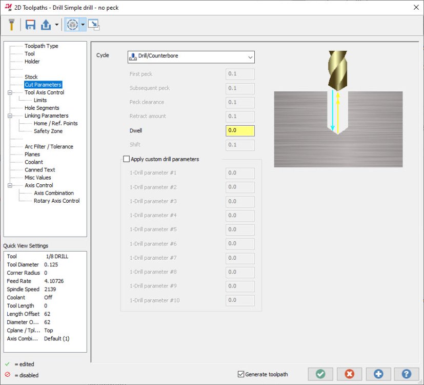
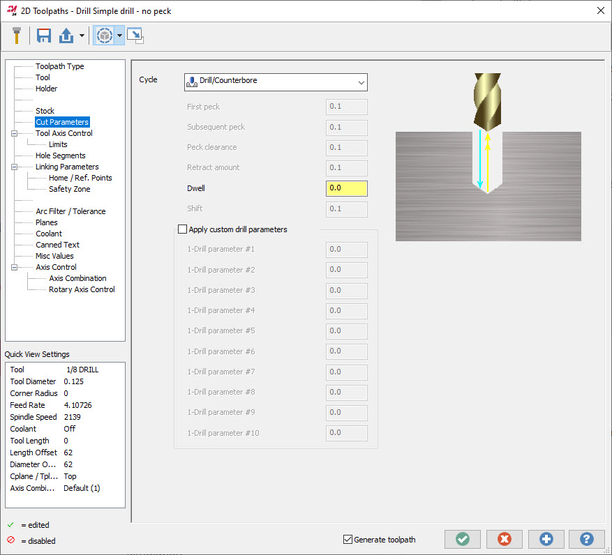
2024 has been changed to allow more room for all of these labels in a slight reorganization of this page:
-
Using deburr locked to 3 axis, and set to flank cutting, will generate back-chamfering paths in 2024 with dove-style tooling fairly painlessly. We do see the need for a dedicated back-spotting/back-chamfering holemaking toolpath that also supports flip-out style centrifugal/hydraulic/coolant driven tools for these scenarios.
-
6
-
-
I believe the alternative, and the reason why this was changed, was the dreaded accidental move of an op in the ops manager that would wipe out the structure of what you were doing. You'd move something by accident by holding the left click down too long and making a slight mouse movement, and not know what was moved, where it went, or where it originally came from, because the move was completed as soon as you released the mouse. The move before/move after menu not only gives you a chance to change where the op is inserted- it gives you a chance to cancel if the drag was inadvertent.
-
5
-
-
1 hour ago, SlaveCam said:
Another one of these nasty undocumented features. At least the op should be marked as DIRTY; it's easy to forget to regen after changing something and then mess up because in previous version (2021) it worked ok without regen.
What toolpath types have you experienced this with? When you went in to change misc values, were you performing any other work, or did you enter, change misc values, and immediately exit the toolpath?
I added a +1 to R-33833. If you have a file/workflow where you can reproduce this repeatedly, please shoot me a message.
-
I looked into this- thanks for providing a file JTaylor. As you described, deleting the viewsheet from the group without ungrouping it will cause a database issue. Mastercam recognizes this and does not let you save the file past this point- there's no danger of corrupting the file. It was found and addressed in 2024, as you also mention.
-
You can use stock plane changes to apply a transform to your stock model to do things like physically move the stock between vises, or tombstone pockets, or even between a lathe and a mill setup in the same part file. Here are some examples:
Here's part 1, which goes through the method you're probably familiar with, which is leaving your part/stock model alone and using different planes to set up different operations. It also discusses basic areas of where and when to use stock models to target operations.
-
1
-
2
-
-
What I was talking about will affect you as you open different part files in a single instance, as well. The settings can overwrite each other in that external file.
-
1
-
-
2 minutes ago, Jobnt said:
I will use which ever method will prevent me from having to re-set my settings in simulator options to select what I want to use.
Every time I open a different file I have to re-set the stock. I'm probably doing something wrong 'cuz I'm fairly ignorant.
This is because those settings are essentially being written to an external file that Simulation looks at when you launch into. You'll notice this especially when you have 2 instances of Mastercam open at once and you're bouncing between them, simulating in both. The settings will keep on overrunning each other.
2024 has numerous changes to the location of these settings in the background, to keep them stored on a per-machine-group basis, not even just a per-part-file basis.
-
2
-
3
-
-
If you're using stock models for roughing purposes, remember to back off the tolerances! The default tolerance for a stock model operation initial shape and tool shape is 0.001"/0.025mm, which is great for a view of the result of a finishing operation, but orders of magnitude overkill for what you need to drive a roughing path that's probably leaving 0.020" stock-on. Use some common-sense ratios and loosen up your tolerances based on what your roughing paths are actually doing, and you can claw some of that calculation time back.
-
1
-
3
-
-
Keep in mind that even the behavior change this shows in Verify/Simulation is still just a guess. Doglegs exist because the machine is allowed to move each linear axis independently, at its maximum acceleration/speed, to achieve that component of the positioning request. So, the motion of the dogleg is highly dependent on the individual acceleration rates of your machine axes. Have 500lbs of parts and fixture on the table? The acceleration of the X axis might be slower now, and your dogleg rapid move changes shape because the X axis completes its component of the G0 much later than it did with an empty table. These are things that can never be properly simulated because the machine position is inherently uncontrolled during the move.
CNCAppsJames mentioned the ultimate way to fix this if its possible for you- don't allow dogleg motion to exist at the machine.
From a programming perspective, anytime you see yellow rapid moves and they are at or below the highest point on your part or fixturing, your antennae should be going up and you should be examining these moves to ensure there's no chance that the volume the tool is traveling through can hit anything if it does indeed dogleg.
-
1
-
5
-
-
7 hours ago, Tegheim83 said:
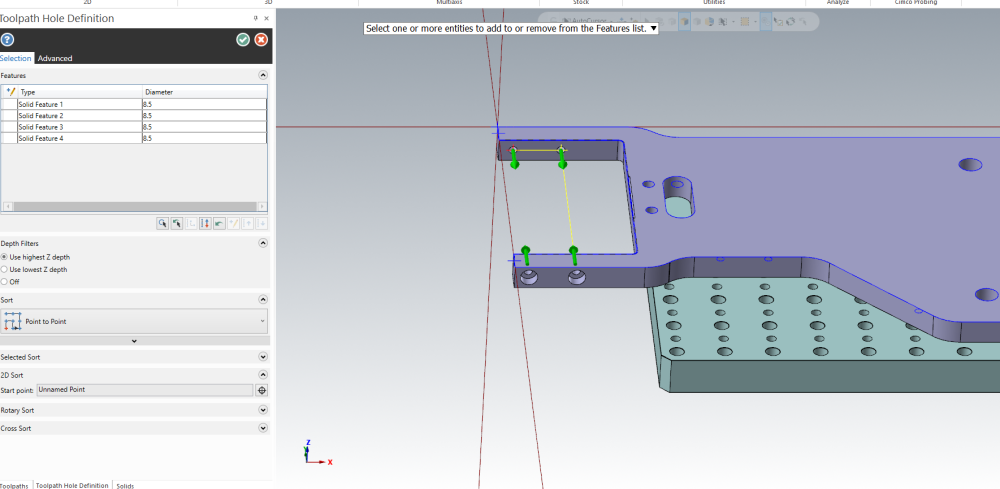
Today I only moved a solid body in one direction.
Obviously the drilling needed to regenerate.
When backplot I noticed that something had changed, and it wanted to drill all holes from the inside instead.
@Chally72, you still have the tickets on this already as R-32862 right?
Lets look forward to update 4 on Mastercam2023.gif ":)")
I added a +1 to this item for you. This is a very difficult problem we're still exploring- a fix will not make it into Update 4.
-
1
-
-
5 hours ago, Thad said:
Yes, I do see that. Here's my problem:
Try the Translate Vector From/To option. Press Reselect. A visual cue of the center appears but it's not selectable to be the From location.
Ah, I see what you mean in 2023 for specifically that Vector From/To control. The CAD team apparently tagged this one as well. In 2024, you're able to grab that center of mass at any point in time during the Vector From/To process.
1 hour ago, TERRYH said:we are on 2023 update 3 we stay current hoping at least a small portion of the stuff we find and report will be fixed.
I can't get that option to NOT stick when I test it. Back to Colin's points- perhaps there is an issue with your workspace file that's the root cause of this. If you delete (or move, so you can move them back) your workspace files and allow Mastercam to recreate them fresh upon startup, do you still have this selection issue?
-
1
-
2
-
-
On 2/17/2023 at 6:42 PM, Thad said:
Again, going from memory...
When you rotate or scale, there's a center of selection (checked by default - I like it!) as the From option (or center of rotation option). But when you Translate, the option isn't there. A visual cue of a point will appear at the center of selection, but it's not selectable. It used to be selectable.
In 2023 and 2024, I have the "checkered ball" center of selection/center of mass available for Translate and Rotate both, and if I start to move the translate/rotate gnomon controls, the checkered ball appears and I can drop the gnomon on the ball. Is this something you can't see/select?
-
34 minutes ago, Thad said:
One of my many gripes for 2023. I recently updated from X9 to 2023 so I don't know how long this has been going on.
Solids- Boolean-Add: User is prompted to select Target body. User clicks Target body. User is prompted to select Tool bodies. User clicks the first Tool body. ERROR! User has to right click in the box on the left, click Add Tool body, then click Tool bodies. (Going from memory so some of the verbiage might be off)
No, this isn't the end of the world, but how about some consistency?
This one I can confirm is fixed by the CAD team in 2024. You no longer have to go over and click in the panel and can immediately go and add tool bodies.
-
2
-
1
-
-
Terry, I tried and couldn't repeat this in 2023. I'm on Update 3. What version are you on?


How do you download the latest public beta?
in Industrial Forum
Posted
Correct- ability to mass edit only WCS, C, or T and leave the rest untouched is new for 2024