Bill Henderson
-
Posts
260 -
Joined
-
Last visited
Content Type
Profiles
Forums
Downloads
Store
eMastercam Wiki
Blogs
Gallery
Events
Everything posted by Bill Henderson
-

Using Metric Tap in Standard Unit File
Bill Henderson replied to Bill Henderson's topic in Post Processor Development Forum
It was my error I see. Reversed the pitch. Dope. -
Using Metric Tap in Standard Unit File
Bill Henderson replied to Bill Henderson's topic in Post Processor Development Forum
Thanks John. -
This may be easy like NO you can't do that, but... I have a model that has both standard and metric tapping. I grabbed an M6X1 tap from the metric tool library and in verify the tap was HUGE so I opened the tool edit and redefined it as 6*.03937 and did the same with the pitch and saved it. However when I went to post the rigid tap cycle out my FPR was 25.4 . Yikes! Is there somewhere in the post that is calculating this? Machine/Control Def? Shoudl I just stay away from mixing metric tools in with standard units? Any help or insight would be appreciated. Thank you.
-
Non modal for X Y callout each line
Bill Henderson replied to Bill Henderson's topic in Post Processor Development Forum
Thanks John. Yes I tried that but it erred out on me. I got it me believes. -
Non modal for X Y callout each line
Bill Henderson replied to Bill Henderson's topic in Post Processor Development Forum
I think it may be pfxout and pfyout but I am still looking. -
Good morning, I have edited a generic 3axis post for a very weird Bostomatic Graphite machine. Is there a place in the post that will force a X Y positional callout at every G2 G3? I looked at the control def etc... It seems I have run into this before years ago, but I seemed to have forgotten. Thank you for any help..
-
Awesome. Thanks Mick. I too had been asking about this since A.R. came along.
-
Dire need of help
Bill Henderson replied to Bill Henderson's topic in Post Processor Development Forum
Thanks guys. It is the .psb I am trying to find. Problem being these (two) companies merged together about 2 years ago. Nearly all of the programmers have since left. The two that remain are Gibbs guys. I have my reseller looking into it for me. Very irritating. To say the least. -
Dire need of help
Bill Henderson replied to Bill Henderson's topic in Post Processor Development Forum
Thanks Ron, Does the machine def control anything on the output? I used the machine sim and everything goes the correct way. Backplot shows negative X values. I have A axis on the table which rotates about the y axis. On that I have a C axis which rotates about Z. I have chosen every different possible axis combination in the machine def and it always posts the same. Pulling my hair out. Job has to run Monday. -
We had a programmer here who used to post to our robodrill 5 axis. However, I think when he updated his machines and post as time went on he kept them on his "box". I can NOT find anything to use. I tried running update utiliy on a post he had but it keeps saying psb missing something or other. I am trying to get a machine/control def to work but it is giving me inverse codes. For instance, the A can only go to positive 90 (rotating about Y to the left from operators POV)( hence making all X locations negative). I get A-90 and X(s) positive. NOT good. The other odd thing I get is the C . I know A90 and C 90 are my first operations but could only get the code to show A-90 C180... what the? I am of course too short for time to run this by our reseller. Job is hot and already on the machine. Any ideas? Thanks. Bill
-
experience with HAAS T5C 5 axis
Bill Henderson replied to Bill Henderson's topic in Industrial Forum
Thank you. -
Just curious as to what anyone's thoughts are on these as far as accuracy, rigidity, etc... http://www.haascnc.com/mt_spec1.asp?id=T5C&webID=5AXIS_RT_ROTARY#gsc.tab=0 We had them on our Mori's and really never seemed to have an issue, but a co-worker said he had nothing but issues with repeatability. Thanks for any input.
-
single pallet? we have a dual on the makino and it is running constantly. Mostly short 50 part type runs. tools we try to keep in carousel to negate resetiing everytime. the ec400 is the overflow machine with single pallet. we try to utilize fixturing for the tombstones so most of the setup is done outside of the machining window.
-
I guess we are getting a new Mori Lathe. NLX 2500 MAPPS IV controller Anyone familiar with this? Sending a request to our reseller for a post. Is there any tinkering or mods I may have to do to use this machine to it's full capability? Supposed to be here after the new year, probably February. Any thoughts or advice would be appreciated.
-
That is what I was figuring... end result would be compound angle. Fixture is mounted...casting secured on fixture. Surface (W) to be flat is in (parallel to table) has to be rotated in B and A . Therefore when (Surface is parallel to table) A may be 5 degrees and the X axis is now skewed to whatever B (10 degrees lets say) became to make (W) flat. If A is "zeroed" at said 5 degrees... the entire program would have to run skewed to the 10 degrees the B has been rotated. Does that make sense?
-
Thanks Ron
-
Been wandering around looking and stumbled across this thread. We have numerous castings that will be coming in. Three datums ar on the NON machined side of the casting. We have four tabs that will be machined on that side to establish points for finishing opposite side. On teh HAAS 5 axis We are trying to see if there is a way to run the probing cycle with a macro to set our A ( datum to be flat) and B rotations (mostly needed to get A datum flat. Once that is set we need the program to run on the skewed B angle. (with just one posted program) From what Bob was saying it is possible. We have a Hermle that will do it easily, but it is bottlenecked. Any help would be appreciated.
-
Thanks Chris. That seems to be where the z value is called from for WCS.
-
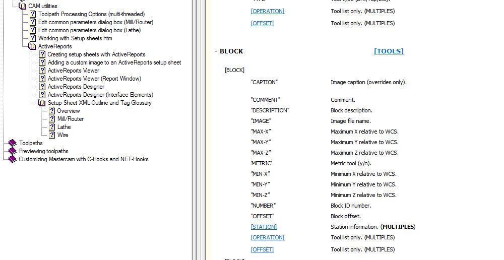
I can get z depths if I use "depth" from the operation, however this ONLY works if you use an absolute value. Incremental (0) for instance will show the depth to be ZERO. The help shows a z value under -BLOCK that is supposed to be from the WCS value... I can NOT find -block in my bounded fields.

-
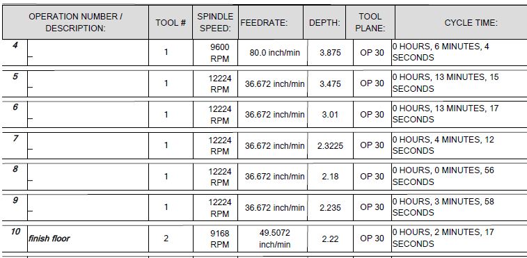
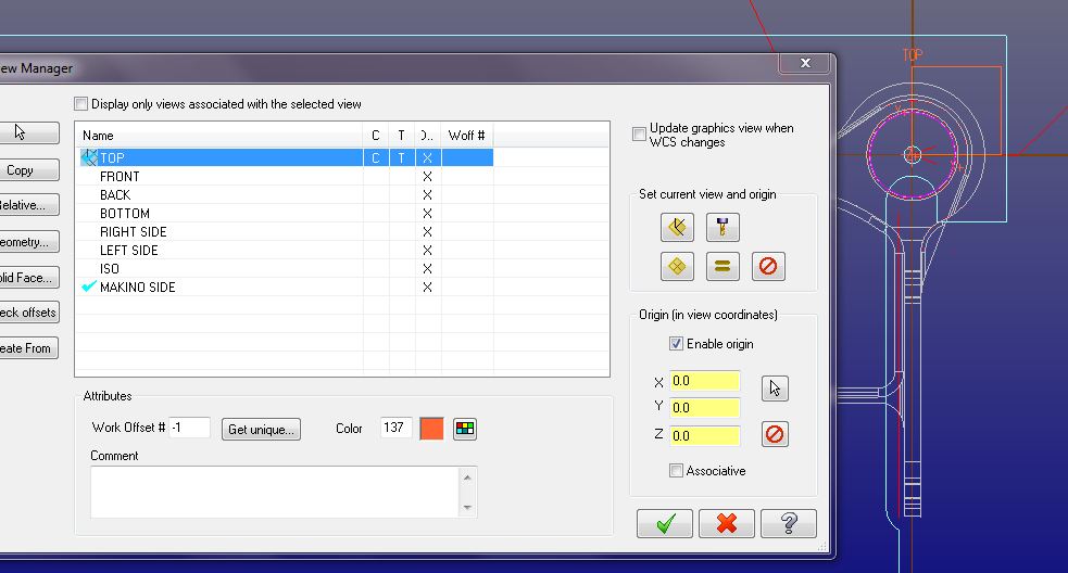
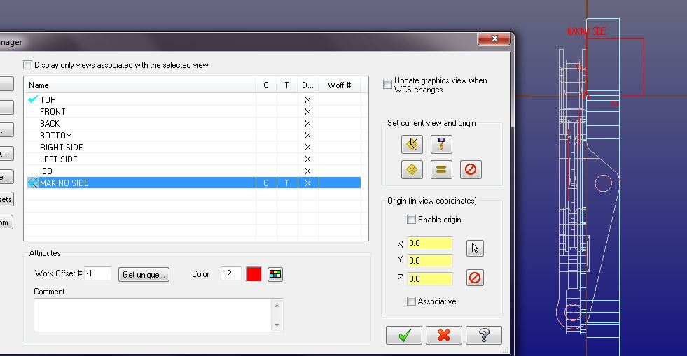
I created this setup sheet a while back. It works great if you have your data moved to Origin. How do I get the max z depth to post correctly if I leave the data in it's native position? I have tried to go thru Offsets/ Tools/// etc... but it still defaults a value from Origin. In this case the WCS T/C plane is 2.600 above the actual origin and the Z level cut is at zero. I want that z level position called out. I seen the calculation fields below bounded...have no idea how to use them. Any suggestions? Thanks. Oh... and its a real issue when you are programming 4th axis on a tombstone and part origin is 14 inches from acutal origin. Yikes.

-
Take a look right here... http://www.emastercam.com/board/index.php?showtopic=71096&hl=locations
-
Horizontal 4 Axis HMC
Bill Henderson replied to Bill Henderson's topic in Post Processor Development Forum
That's the probelm when you have 8 different flavors of machines and any given day scheduling moves a proven program from a VMC to an HMC. I got it to work by leaving the WCS set at TOP and t/c planes to front and right. Front being the initial B (0) and right going 90. Probably why I had issues running simulation and my tombstone was set sideways. DOPE Thanks Ron -
Horizontal 4 Axis HMC
Bill Henderson replied to Bill Henderson's topic in Post Processor Development Forum
I established my Makino right t/c plane as if the top "was " front. If that makes sense.

-
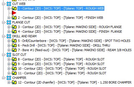
I have first ops running from the top wcs... with subsequent ops from right side... Using the generic 4 axis hmc and fanuc pst... I am getting this... ( ROUGH WEB ) T1M6 G0 G90 G54 X1.6293 Y-.9623 B-90. S611 M3 G43 H1 Z6. Z.516 G1Z.368 F3.66 G3X.9222 Y-.9514 R.5001 F4.89 G2X.5308 Y-1.214 R1.325 G3X.39 Y-1.4293 R.235 G1Y-2.4 G3X.89 Y-2.9 R.5 G0Z6. M5 G91G28 Z0. B0. M01 The B value should be at zero (top wcs) and the B-90 for right side.... (which by the way it does post out). What am I missing? I used this same hmc and pst for another multi rotational Makino program and it posted out fine. A bit baffled... Probably overlooking the obvious. Thanks for any help.

-
This what I was sort of looking for in my "new topic" I posted earlier today. Seems the link(s) is dead.