rsc
-
Posts
19 -
Joined
-
Last visited
rsc's Achievements
")
Newbie (1/14)
2
Reputation
-
They are there, listed as "N/C Counterbores". The 2012 PDF catalog I'm looking at has them on page 67. They are flat bottomed and center cutting. The size range is 3/32" - 3/4". Bob
-
Try Internal Tool Inc. Website: http://www.internaltool.com/ Good luck. Bob
-
Look into the following website. They have an online video library for $25/month. Online classes are extra. http://www.eapprentice.net/ Good luck. Bob
-
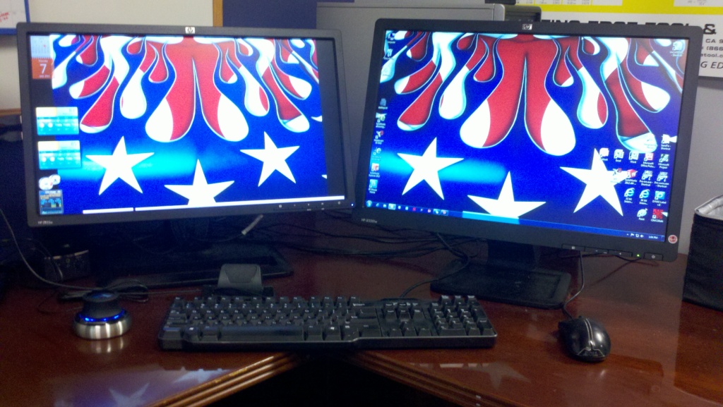
Running dual monitors here. One 22" and one 21.5". I wish both were same size and resolution, though. One is a had-me-down, so I should be happy I even have two! I'm also using a SpaceNavigator. I'm not sure one of the other versions would do me much good since I don't even use the two buttons on the basic unit. Those of you that do use the buttons, what do you have assigned to them? Bob

-
There are two possible paths when making an arc using R values. The controls I have worked with will always take the short path (an arc under 180 degrees) at a given unsigned R value. If you need to take the long path (greater than 180 degrees), you need to specify the R value as a negative. As you can see, using an R value can lead to a bad cutter path. I prefer to use IJK because there is no question where the arc center is. When I learned to write G code 35 years ago using pencilCAM (paper, pencil and calculator), there was no R programming. Everything was IJK. The first machine I programmed that used R programming was a HAAS. I used it successfully until I had to do an arc greater than 180 degrees. It followed the short path. I changed it to IJ values and it followed the correct path. Examination of the manual showed me I had to use a negative R value for greater than 180 degrees. I have not used R values since then. Bob
-
Hi Marshal. Check runout of the stylus. It should not be more than .0002 TIR. There should be four screws (spaced at 90 degrees) at the top of the probe body that will allow you to push the probe body around on the probe shank (similar to a Buck chuck on a lathe). Remember to back off the opposite screw before trying to push the body in that direction! Where I worked previously, my department got the first machine (HAAS horizontal) with a probing system. No one in the company had any experience with probing, so I was on my own. I found out quickly that you need to check it regularly, especially when the night shift fellow breaks a stylus and replaces it without notifying you! When calibrated properly, it worked great! I used it regularly for setup and in-process fixture offset setting. Out of calibration and you are asking for trouble. On the HAAS system you need to calibrate several aspects of the probing system. First, check runout and adjust as described above. Next, calibrate diameter using a gage ring. Next, calibrate the length. That should do it. I hope this helps. Bob
-
1:50 HP Z400 Workstation Intel Xeon W3503 @ 2.40 GHz Seagate ST3250318AS 6 GB Ram Win 7 Pro 64 bit Nvidia Quadro FX580 Win Experience Index 5.9 (overall) (Processor = 6.3) (Memory = 7.5) (Graphics = 6.4) (Gaming graphics = 6.4) (Primary hard disk = 5.9)
-
Thanks for the information. Speaking of posts, can you tell me who can supply a good post and machine definition for this machine (Nakamura Super NTMX)? Bob
-
I have not seen a demo of Camplete, so I can't tell you exactly what it can do. However, from reviewing their website, I guess you could program within their G-code editor, just like you could in Notepad, but you would have to generate the code by hand. The way I understand it, Camplete reads the G-code generated by a CAM system (Mastercam, Gibbs, etc.) and will simulate the machining process. If changes are needed (wait codes, reorder tools, etc.), you can do that within their editor, then rerun the simulator. Bob
-
Vise on turret for mill/turn machine?
rsc replied to rsc's topic in Machining, Tools, Cutting & Probing
Do you think it was a one of a kind, custom built vise? Thanks for your time. Bob -
Vise on turret for mill/turn machine?
rsc replied to rsc's topic in Machining, Tools, Cutting & Probing
Hi Chris. We don't have the machine yet, so I can't even tell you the axis designations. The machine is a Nakamura Super NTMX mill/turn machine and it has a lower lathe turret with live tooling, a tilting milling head, left and right lathe spindles with rotary axis ability. For parts that are difficult or impossible to pick off in the right spindle, we are hoping we could use a vise mounted to the lower lathe turret to pick off the part and maybe do some additional milling if needed. We were told such a vise is available, but we don't know who makes it. We will meet with the Nakamura apps people next week. Hopefully they can tell us if it actually exists. Thanks for you help. Bob -
This may sound a little crazy, but is there such a thing as a vise that mounts on the turret of a mill/turn machine? I have been told there is a vise that mounts on the turret and is accutated by coolant pressure. The vise could be used as a pick off station and allow machining while clamped using the coolant pressure. I searched the internet, but found nothing. If there is such a thing, who makes it? Thanks in advance. Bob
-
Our company is purchasing a Nakamura Super NTMX Mill/Turn machine. Does anyone have experience with Mastercam and this machine? We are new to mill/turn machines. It will come with Camplete for simulation. We would like to use Mastercam X5 for programming. Is it possible to program this machine with Mastercam? Will we have to program in sections (for example, program the turning portion then the milling portion), then combine the posted code into one program and simulate in Camplete? Alternatively, is our best solution to get Partmaker? Thanks in advance. Bob
-
Dakota, Bingo! That did it! Thank you for that tip. You would think there was an easier way. For example: 1. In Operations Manager, click on the toolpath in question 2. Click on Geometry 3. In Chain Manager, right click on the chain 4. Chose Analyze Chain Besides the other info about that chain, it would be nice if it indicated the level the chain is on. Anyway, thanks again for the info. Bob
-
Is there an easy way of determining what level a toolpath chain is on? In the Operations Manager, when I click on Geometry for a given toolpath, the arrows show the direction of the chain and compensation side. If the level that contains the chain is off, those arrows are basically are just hanging in space, attached to nothing. When I have multiple levels containing geometry, I have to turn levels off and on to find the level that particular chain is on. I tried looking in the chain manager, but found nothing to indicate the level the chain is on. How do I easily determine the level that chain is on? Thanks in advance for your help. Bob