


.jpg.8806641f469cc0e42e295fe41eeecf5a.jpg)
CNC_Newbie
-
Posts
72 -
Joined
-
Last visited
Content Type
Profiles
Forums
Downloads
Store
eMastercam Wiki
Blogs
Gallery
Events
Everything posted by CNC_Newbie
-
.thumb.jpg.d93194e16c52559797e465ed45058040.jpg) Indeed I did. Mastercam.com forums is the one that requires you link your software license to be able to access the forum. Is that forum a good forum. Is it worth the efforts to join that forum? iI just joined the so called Darkside, I look forward to seeing some of you folks there too. For some reason I thought the E in E mastercam forum stood for Europe
Indeed I did. Mastercam.com forums is the one that requires you link your software license to be able to access the forum. Is that forum a good forum. Is it worth the efforts to join that forum? iI just joined the so called Darkside, I look forward to seeing some of you folks there too. For some reason I thought the E in E mastercam forum stood for Europe -
@Thee Byte I see <((*))> <((*))> I have to Link mastercam to my email (or something like this) and to do so, I have to install some sort of utility on the work PC to make that happen. Thus I am not registered in that forum. I dont want to install anything on the work machine.
-
This Video was Fantastic! It explained so much! I can’t thank you enough for sharing his valuable time and invaluable knowledge and skills. Really, it was helpful on so many levels. I’m sure once you get a handle on the OBS software it will go easier for you. Learning axis control basics was fantastic and the fact you took the tine to show how to simplify the generated code fully opened my eyes. What a time saver that will be for the fellow that spends days stripping and patching code. I have so much to learn, but at least I have had a peek behind the curtains and seen the wizard! Colin… you sir are THE MAN! Again, THANK YOU! What is the dark side?
-
Thank you. I will reach out when I am ready. Thanks for offering to help me. I learn so much each day. I wish it was all day everyday Mastercam stuff, but it isnt. Mastercam time only comes at night when I am trying to figure out everything VIA the MC 2020 HLE software. In the daytime I am fighting to install un mapped fixtures, and input correct offsets (10-15 per part) to make these hand coded parts cut parts. Its horrific to say the least! I know a these issues we are having are based on programming. I also know we have 3D models for everything we are cutting. This is the reason I need to learn this stuff quickly. I am tired of struggling with what we are doing. The fellow that is doing the programs now has to spend hours Modding the Posts. Here is an example. He has a model and selects a edge to cut, so he draws a line in the center od the edge, then used curves for a 5 axis 3D tool path, then he selects the line/chain he drew, then he repeats that process making a seperate toolpath for each section of the part he wants to cut, this means a HUGE list of tool paths and lines he as to draw to create the tool paths. insead of using the surfaces or edges of the model as the selection for the tool path. In the end, he will have 18-20 seperate tool paths and hen he posts it, between each toolpath the post has generated a reset or an Unwind that has to be removed in the post editor so the tool wol stay in the cut. I know there are so many ways to do any one thing in Mastercam. If in fact the Programmer has to create new lines vs using the actual models edges of the model and creating new lines via some sort of offset to center the new line vs being an outside edge. What we do is basically cut parts out of a molded plastic sheet that has been formed in 3D. We place the formed parts onto a vacuum fixture and cut it out. Let's say the part thickness is 1/4" and the model shows this 1'4 thickness as an edge of a part, if you select that edge as a face, the toolpath created will cut around the outside edges of the part, but if you draw a line down the center of that 1/4 thick part, you can select just that line and the tool fill cut down the center of the edge via single cut. I am still trying to figure out the basics. I will have to say that (IMO) Mastercam isn't very intuitive. I think you should be able to select a face, an edge, or a line of a model. Tell it to cut here in the center or inside or outside, then select if you want to make the cut horizontal or vertical (using the tip or the side of the endmill). I think you should have loop selection where I can hover an edge on a model and if that edge creates a loop it should highlight and I should be able to select it. Once selected, it should ask me how do I want to cut the first feature, then as the features change, like from a straight line to a radius it should as how I wand the tool to follow. I have used several 3D modeling software packages, 99% were for drawing, and I was able to fumble along and discover how to do different things quite easily. Mastercam is a different animal all together. I will learn this stuff and when I do I plan to make lots of video tutorials helping folks like me who struggle to understand the basics. IE, how to make a selection of a 3D model, how generate a toolpath based on a selection, how to define actual cutter orientation to the part. Lastly how to select multiple edges or surfaces at once and define the control of the tool as described, I know Mastercam can do everything, its trying to figure it out in an clear and easily understood way. I was really hoping that I could find someone on KCMO that would be willing to tutor me, but this isn't going to happen, LOL Long winded ramble.... Over!
-
Look For A Mastercam Peogrammer in Kansas City
CNC_Newbie replied to CNC_Newbie's topic in Industrial Forum
Wow, thank you for offering information to help with my foundational understanding. I appreciate your time very much. -
I hope this is the right place to ask this question. I am looking for a Mastercam programmer in Kansas City that is willing to do a Q&A session with me so I can pick their brain for a little while. I have learned the interface (not everything) and I can place models, Manipulate the models, I can select and deselect, surfaces, edges, points. I can create wireframes, extrude solids, place holes, chamfers, ectt based on a blue prints. I understand the ribbon interface, the right click menu, the back stage, the post folder structure, the basics in the tool path dialog (generating and re generation of tool paths, how to create a post) . Levels, and a bunch of other stuff. I’m struggling to put it all together if that makes sense? Where I struggle is knowing how to actually Manipulate the tool to follow the defined tool paths in the way I want it to. To gain control of the way the tool follows the tool path, and to know which of the settings in the parameters dialog are critical to achieving the desired result. Some times I want to cut vertical (using the tip of an end mill). Sometimes I want the cut to be horizontal (cutting with the side of the end mill) . I’ve been looking around in the Demo software and it’s not apparent how one chooses the B axis is vertical or horizontal on a head head machine. Or is there a setting that I choose in parameters to tell it to follow the tool path vertically or horizontally. Maybe I have to adjust the Gnomon so that Z is horizontal to my cut surface to cut on the side of the end mill (stupid questions that I can't find answers to, that I am sure a Q&A would clear up quickly) I know so have so much to learn, and I am looking for someone in Kansas City who might be willing to share some time with me directly to help me. To be honest it would be amazing to sit and watch someone program and show me the ropes. I can compensate for their time as I know it’s the most valuable asset in life.
-
Sorry for yet another stupid question. At home where I am trying to learn Mastercam 99% of the time, I am using the demo version. I want to try and set up my machine definition as 5 axis machine to I can mimic what we use at work. Am I thinking all wrong? For the machine type can I just use Default Mill as my machine? And the post, Postability 5 Axis Motion Master in our case, defines the actual machine when the code is created at the end? The demo version doesn’t post so, is it a Mute point? Trying to wrap my head around MC is a challenge and sorry for the basic and stupid questions
-
how to force Mastercam to keep tool Perpendicular to Work face
CNC_Newbie replied to CNC_Newbie's topic in Industrial Forum
It will be Monday. I was on the floor all day today doing fixture installs and part set up of a new jobs. This is no easy task as there are zero notes on fixture placement, and no less than 11 offsets that all needs to be adjusted to make this crazy manually created Goode program (created by hand years ago) to work. This place gives no free time for tweaking the process, it’s all about production. I was hoping to fix that issue quickly when the part was on the table. I can’t take the files home, so I’ll have to go in on my lunch Monday to make a photo and video of the tool paths and black plot. I can’t share the file to the public as all of the actual models are protected property via the company and customer So what would be the best way too share a file here that does not contain the actual model? Is it possible to strip the model and share only the tool path? -
how to force Mastercam to keep tool Perpendicular to Work face
CNC_Newbie replied to CNC_Newbie's topic in Industrial Forum
Sorry to jump the gun, lesson learned. Thanks for your time. -
how to force Mastercam to keep tool Perpendicular to Work face
CNC_Newbie replied to CNC_Newbie's topic in Industrial Forum
Thanks fellas! I greatly appreciate all of your tine. If I came off as being Rude, or having an attitude, this was not my intention . I am extremely grateful for all of your time and help. I responded after 7 hours of my initial post. I was just checking to see if anyone had given some advice, saw none, and made a quick response. This part is running 90% well and if so can just figure out the 2 moves on the tool path, I can wrap this part up. I was hoping to figure it out before we pulled the fixture down and moved ion to the next job, but I made notes and will definitely fix this issues. In the coming days I just want to also say, I totally understand that this forum is FREE, and folks help out of the kindness of their heart. I do the same on many other forums where I know much more about the subject at hand. I help anyone who needs it, for free in Photography, photoshop, illustrator, premiere pro, after effects, c4d, maya, blender, post processing, as well as in the UAV world. In short I always try to pay it forward. So I get it, I really do. I hope that in time you folks will see that as I learn this software I plan to help anyone I can that needs help. Again, I appreciate your input, all of you, and I’ll follow up once I figure it out or ask more newbie , less rude, (hopefully), questions. -
how to force Mastercam to keep tool Perpendicular to Work face
CNC_Newbie replied to CNC_Newbie's topic in Industrial Forum
Nadda? -
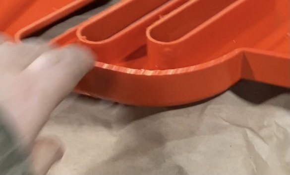
I need to know what the best strategy is to keep a half inch iend mill that is cutting on the horizontal to maintain perpendicular angle to the work face. I’m routing panels and I have vertical cuts and horizontal cuts that exist on the same plane. Z controls the height of the plane. I have noticed that as long as the tool is maintaining a 90 degree angle (on the horizonta cutl) it cuts perfectly. However when the tool passes over the part on a horizontal curve, it does not rotate on the C axsis, only moves the to tool on the X,Y & Z (we are on a Head Table setup) and it chatters on these curves. I need the tool to maintain 90 degrees to the part in the C Axis and keep everything else that is doing. In the photo below you can see the chatter in the part, I just know that if I can make the tool rotate on the C Axis to maintain a Perpendicular cutting angle this will not happen anymore. Everything cuts beautiful where the tool is Perpendicular to the part. I started learning MasterCam less than 3 weeks ago, but I know the answer lives in Multi Axis Control. I suspect I need to place a reference point and use the "Around a Point" option. I know there is a bunch of ways to do ONE thing in Mastercam. How would you folks handle this situation? Thanks for taking time to help a newbie.
-
I sent an email to the reseller and asked for few things. Thanks for taking time with me. You know that I JUST realized who you are! I told you I was doing lots of tutorials. It actually worse that, lol. I have consuming mastercam content every waking moment for 3 weeks trying to catch up and just figure things out. That Logo in your profile, I knew I saw it somewhere. You have been doing this for 30 years! I loved every minute of "Ron Week"! That so called simple part was amazing. The use of "Dumbed Down" stock models is a fantastic idea! You are an INCREDIBLE library of knowledge, I cant believe that it's actually you responding to my posts here. You said in the videos that you like to give back to the Trade and have been helping people in emastercam forums for a very long time (15 years is what I think you said). I took so much from RON WEEK! How you took the 100 hour rough time to 40, how 1 scrapped part is worth 3 and why, How getting it right in the program is how to make money on the floor. I wish I knew more about Mastercam so I could of absorbed it better. I did save all those vids a playlist for safe keeping, I plan to watch them again and again. Never having been exposed to Mastercam, I think I like your screen layout much better than the Ribbon. Ill learn based on the free tutorials and then decide if I want to try your layout scheme as it gives a much less cluttered main window. SHM, I still cant believe its you , thanks so much for taking time to help a complete newbie at CNC like me. T
-
I have never reached out to anyone (dealer). I started this job only with zero knowledge of commercial CNC machines, or software used to produce tool paths. I am trying to teach myself as the other fellow is part time and its obvious he isn't willing to open his mind and share anything. I have built several hobby grade CNC machines, and use Open Source programs to model, generate The Gcode, and to drive he code to the machine via various controllers, Rambo, Tiny-G, Arduino, ect.. I have also done lots of 3D modeling and animations in C4D, Maya, Houdini, Blender, and sculpting in zBrush. The commercial stuff is all new, but I am a fast learner. I walked into this job naver of touched anything and in 1 week I am running the machines, breaking up the code into offsets and manually making these old machines cut where I want them to, I have also been doing Mastercam Tutorials every night since I have started (3 weeks now). and I am trying to get a handle on things so i dont have to keep fighting this old code via Offsets at the console. I want to take the programs down from the drive at the Controller/console and fix them in mastercam (the ones created in MC) and put them back. As to the cable that runs to the machine, its like 60 feet away and it runs from an office through the metal trusses and drops down to the controller. I think using the USB at the controller will help deal with dropped Gcode (due to line loss I guess). Again its hard to understand how we can send a file and not lose lines of Gcode, yet when we retrieve the files from the controller/console it magically drops lines of code (supposedly). I just need to find a rock solid way to move files and not have to deal with unforeseen variables. Peeking through some paperwork in the desk at work, I do believe the place they bought the software from is QTE Manufacturing Solutions. I will reach out to them Monday and try to figure out what I need to do to strip the G53's from the post. The reason the other part time fellow wont go into mastercam and fix the programs is it take him 20 mins to strip the code from the post each time so he just messes with the code editor at the console. He's always in a rush, as he is only there for a couple of hours in the morning after he as already worked a full shift at his other job. He's a nice guy, but he's already tired and it clear he wants to get the parts running and get home, (we have 2 machines). The way the place has operated for years is get the parts cut out with 90% of the rough dimensions cut with a .030 tolerance and grind/hand finish each part to get out out the door. I just know I can do better and I am willing to learn what it takes to make things run correctly. All in all it has been a crash course in patience knowing that the sooner I learn the right way to fix these problems the easier things will go and the faster I can move up and train a button pusher to put on, cut, and take off a good part without having to fight tooth and nail to get setup and running. This place has amazing potential, someone just has to take ownership and learn, this is where I come in, I just found this to help me explain the "Reals and Integers" https://postability.com/miscvalues
-
I think I have a workaround for the Dropped File issues. There is no way I can get these folks to spend money or rewire this controller to bring the PC closer to controller. What I plan to do is simple. I will use the USB connection on the front of the terminal to put and pull down the files. It is so strange to me that the PC can send the files no problem, but pulling them down,"they lose lines". I MUST have a ROCK SOLID reliable way of putting up and taking down files. Especially when I get to the point of using mastercam solely to make edits to refine the tool paths during setups. I dont mind an offset or 2 to make simple corrections based on variance in the actual molded parts, but spending a day to a day in a half trying to break apart blocks of Gcode that arent notated/defined clearly and assigning different offsets to take control of a tool path that is clearly off in the program is ridiculously frustrating. Is there some sort of setup/parmenter's code that needs to be modified in mastercam that can only be addressed via the Software Dealer? I see many simulations running in Youtube Mastercam Tutorial videos that show an animated 3D model representing the actual Machine and its parameters that are running the part programmed in mastercam. I see there are libraries that allow you to define the tool holder. We use a collet and a nut to hold the tooling (like a huge dual spindle router, it is a router on steroids). How do I define the actual Motion Master SB55 in Mastercam? Also do I need to define the Fagor 8055 controller as well and will this help with the G53 issue? I read in a different forum running a different software where some code (like python or something) had to be modded to fix the problem. Is this the kind of thing the dealer will have to help us with? "Your control requires a #MCS block to move the axes to an absolute machine position rather than the G53 block. You can change everywhere in the post that references 'gFormat.format(53)' to use "#MCS" instead. There is one instance in the onSection function and 3 instances of this code in the onClose function. Your changes will look like the following." In onSection() writeBlock(gAbsIncModal.format(90), gFormat.format(53), gMotionModal.format(0), zOutput.format(machineConfiguration.getRetractPlane())); // retract In onClose() writeBlock(gAbsIncModal.format(90), gFormat.format(53), gMotionModal.format(0), zOutput.format(machineConfiguration.getRetractPlane())); // retract zOutput.reset(); setWorkPlane(new Vector(0, 0, 0)); // reset working plane if (!machineConfiguration.hasHomePositionX() && !machineConfiguration.hasHomePositionY()) { writeBlock(gAbsIncModal.format(90), gFormat.format(53), gMotionModal.format(0), "X" + xyzFormat.format(0), "Y" + xyzFormat.format(0)); // return to home } else { var homeX; if (machineConfiguration.hasHomePositionX()) { homeX = "X" + xyzFormat.format(machineConfiguration.getHomePositionX()); } var homeY; if (machineConfiguration.hasHomePositionY()) { homeY = "Y" + xyzFormat.format(machineConfiguration.getHomePositionY()); } writeBlock(gAbsIncModal.format(90), gFormat.format(53), gMotionModal.format(0), homeX, homeY);
-
Hi folks. I am deep into learning to run this old Motion Master SB55 (5 Axis CNC) with Fagor 8055 controllers. I work at a Thermo Plastics company and we mount 3D molded plastic parts to fixtures and cut the parts from the excess materials left in the forming/molding process. We put holes, cut outs, notches, radiuses, slots, ect, ect into the parts while vacuumed down to the fixture on a table that moves on the X axis, the gantry does Y on a long ball screw, the Z is moved via an Air ram, and B and C are geared. I am pretty new to all of this, however I am learning fast. Basilly inside the Fagor controller lives a CAM software of sorts and one basically programs parts to run in the termal using "profiles" where you define parameters, it has canned G Codes, and you use the terminal to program all the parts. Then use Offsets in the terminal to control various blocks of code (G54, G55, G56, G57, G58, ect) you can spend all day trying to set up a part based on these offsets. Each job has a folder and bacilly you open the file and it defines the tool size and stick out, the fixture placement (some of the times they dont note this), then you are supposed to type in all the offsets from the previous run and tweak based on whatever is needed to make a grindable part. Its really a dated system, imo, but they make parts for many big companies. Now on to mastercam. They have a seat of mastercam 2020, and they had a fellow spend a couple of weeks poking around in the software and he was able to program a 3D model in to tool paths and post it. However he never really defined the machine in any sort of great detail. He said he just input center axis points and distances to defne the machine. I am not exactly how defied the tool paths, he used faces of the model in some places, chains in other, he used lines in some places, I am sure this is pretty normal stuff. However when he posts the file, he has to spend an hour or so stripping stuff out of the Gcode. I think he must of removed 100 G53 codes among others. I am wondering if part of the code that is being posted that has to be taken away is because he didn't define the machine correctly in mastercam? I am still doing tutorials daily at home in mastercam, and I know just enough to be asking these Stupid questions as I fight to bring this 5 Axis Antique into the modern times. Lastly, is it possible when taking programs down from the Fagor 8055 back into the PC to lose lines of Gcode? If so, like hs says happens," Alot", how does one backup all of the actual working files that live at the controller terminal? The way we move files up and down between the PC and the Controller is via a Program called WINDNC, and it's like working in windows 3.2. They have a RS232 port to a cable that runs to the Controller, and on the PC side they have a RS232 adapter to USB. Personally I think an Arduino, Rambo, or TinyG controller has more horsepower when it comes to computing, but this is a whole other can of worms, I am so sorry for the long drawn out description of my situation. I just want to find out the best way to define this Hardware setup in mastercam so that when I make a post that I am not digging through the Gcode stripping out stuff that is going to stop my files from running. I have seen in many Mastercam tutorials where the machines are defined, the head, the table, spindle, the tools, even the sheet metal cabinet workspace is defined so that when they slinging tools around in there is a defined safety space. Not to menton, you can play a simulation and see everything the tool is going to do to a stock model? Right? I hope I am not asking to do the impossible here. I am just trying to give myself as much chance for success as I really try to learn this trade. I appreciate everyone who takes time to read this windy post and can try to help point me in the right direction. PS, please use the smallest spoon you have when feeding me information as I truly am a CNCNewbie
-
Thank you
-
Is there an option to toggle the Gnomon visibility on and off? I want to hide it sometimes. How does one hide it and bring it back when wanted?
-
Just in case anyone has this problem, I fixed it in the Mouse properties menu of Windows. I searched Microsoft Mouse in windows explorer, I disabled (unchecked) horizontal scrolling in the wheel options, and I disabled the zoom button that is located on the side of the mouse. Now my Microsoft mouse zooms in and out as it should, not just zoom away in both directions.
-
Fantastic response! There is another fellow that has been a button pusher at my place of employment for 6 months and he is clueless. In 1 week I have all but taken over the CNC area. He is always comming over and asking me to read the prints and verify his measurements. He is always struggling to determine which direction to make a move in the offsets as he doesn’t realize exactly how these machines work. I asked the boss to take home the Fagor manuals and have already read all them. I ha e a firm grasp of what what adjustments to make in order to make the machine move and correct what I want it to do. However I need to learn to program it as the way they run are just wrong. They tooL paths are off and I just need to learn the MasterCam software package I order to fix the existing programs, as well as program future projects. I was hoping mastercam was like many of the other vector programs I have used in the past. I was hoping for a Pen tool what creates splines with the ability to add points and remove points and used as a tool path. I was hoping one could freely drag the points around in 3D space in relation to faces of a 3D models geometry. I bet Mastercam can do this, but I am afraid I’ll just ha e to start at the beginning and make silly blocks with holes and chamfers. With thermoplastic parts, it’s not like traditional millinG where you remove material in order to make a part. The part is there, you just need to locate faces and cut radius, holes and lines to remove the part from molded shell. It’s more like 3D routing than it is actually milling anything. the machine is a 5 axis mill/router made by motion master
-
I work at a Thermomold Plastics company where we have a Dual Table 5 Axsis CNC router/mill machine. They are old machines that use Fagor 8055 controllers. 99.9% of all the programs have been written in the Fagor CAM software where you generate code based on editing profiles and calling up and defining canned operations. Then we basically use the G code to and a Bunch of Offsets to correct the tool paths to compensate for part variances in the mold making process. The parts are molded, loaded on fixtures and we cut the parts into the final shapes, make holes, cut grooves, ect ect... So we have a seat of Mastercam 2020 and I need to learn how to create tool paths and to be able to manipulate the paths easily and quickly when cutting out the parts from the molded shapes. Also I would like to find a way to convert the old Fagor Gcode files into mastercam and generate tool paths that I can also easily manipulate. I have worked with many different software packages, All of the Adobe Suite, Photoshop, Illustrator, ect... I have also worked with several 3D Motion graphics software packages, like C4D, Blender , Maya so I am familiar with solid geometric modeling and vector graphics. I know these softwares dont compare to Mastercam as they dont generate Gcode and dont interact with tooling or machines. I have also built several 3D printers and a couple of Open Source CNC 3 Axis CNC machines (OX CNC) which is a scaled down version of the Motion Master, Fagor controlled machines I run at work, In the open source CNC world I used Stuff Like Tinker CAD to create the geometry, Simplify 3D slice and generate Gcode for 3D Printing, JS Cut for Generating Gcode for the CNC router/mill, and a web browser based control software called Chilipepper to run the Tiny G motion controller for the CNC router/mills that I have built. With that long and painful story explained, I know now I am in the big leagues. I told the man that Hired me a week ago that I can run any machine, and learn any software package if he gives me 6 months. So, here I am asking for guidance on where to begin. I dont need to worry about creating geometry at the moment. I just need to take the models that the customers provide, make selections of there I want the tool paths to be, and I need to be able to plot Points like a 3D vector graphic. I want to be able to click and drag the points along the paths to modify their positions at will. Then generate G Code and post it to the machines for testing and tweaking, IN MASTERCAM, not via Offsets at the machine console (granted I understand offsets are helpful for corrections based on manufacturing variances). I also understand that Mastercam does a ton of different and amazing things in the CNC world, for now I need to just focus on creating and manipulating tool paths based on 3D models, and generating the Gcode I am a very driven individual, and I have a ton to learn. Where do I start? Is the best place Mastercam university? I was hoping to find a bunch of Mastercam free TUTS on YouTube, but there aren't many step by step open source education programs available for Professional CNC/CAM softwares like MasterCam. Thanks for your time and wish me luck on Crash Course learning of Mastercam 2020 and commercial CNC machines. PS I have peeked at a part supposedly programmed in Mastercam, he said, "I used Chains", but he has no idea of how to add points, move points, or minulate the tool paths in any way. I messed with his program for a little while hoping there was a way to select a point on a tool path, and to drag it around like I can in many other 3D mesh or vector based drawing packages. But no luck. I did see he edit toolpath dialogue pop up menu/box, but this only allowed me to add a point or delete a point. I was looking for more of a Visual way to work with the tool paths. Maybe right click add/delete point, some sort of snapping functions that will snap to a line, a face, an edge, ect.. Ill ask this again, where to begin?
