Darin
-
Posts
285 -
Joined
-
Last visited
Content Type
Profiles
Forums
Downloads
Store
eMastercam Wiki
Blogs
Gallery
Events
Everything posted by Darin
-
Hi, We have a You-Ji vertical live tooling lathe.. I need the post to put a Q on each line when using G83 peck drilling cycle.. Where in the post is this controlled? I am not sure what the original post was or came from.. Here is the top of the post POST_VERSION] #DO NOT MOVE OR ALTER THIS LINE# V15.00 P2 E1 W15.00 T1337895755 M15.00 I0 O0 # Post Name : YOU JI # Product : LATHE # Machine Name : YOU JI # Control Name : OI # Description : YOU JI C-AXIS POST # Mill/Turn : YES # 4-axis/Axis subs. : YES # 5-axis : NO # Subprograms : YES # Canned Cycles : YES # Executable : MP 10.0 # # WARNING: THIS POST IS GENERIC AND IS INTENDED FOR MODIFICATION TO # THE MACHINE TOOL REQUIREMENTS AND PERSONAL PREFERENCE. # # Associated File List$ # # GENERIC FANUC 4X MT_LATHE.control # # Associated File List$ # This is what it posts out now for G83 peck drill.. N1 M01(17/32 DRILL) G00 G18 G40 G80 ( DRILLS WITH 17/32 DRILL ) G00 T1010 M06 M69 M22 M41 M66 G00 G54 X9. Z.1 C0. M08 G97 S1500 M33 G98 G83 Z-1.675 R.1 Q.1 F5. C90. <------------------------------------------------------ Need a Q.1 on each line -----------------------------------> C135. <----------------------------------------- Here --------------------------------------------------> C180. <----------------------------------------- Here --------------------------------------------------> C270. <----------------------------------------- Here --------------------------------------------------> C315. <----------------------------------------- Here --------------------------------------------------> X0. C90. <----------------------------------------- Here --------------------------------------------------> G80 M09 G00 Z2.0 M35 M21 G28 W0. U0. H0. T0000 Thanks
-
Hi, Is there a way to make Mastercam default to slice not spin with turn profile? We have had issues with using spin and properties solids . The geo is off sometimes .002 or .003... Never fails with slice.. We have X6 and Solidworks 2012..

-
Hello, Where in the post do I need to edit to add the pop up to have it ask for the programmer name when it posts? Thanks
-
(1.) Make sure that the tool # and tool height and Dia offset are always linked no matter if you change it in the parameters page or tool page. So if you change either the tool # or height or dia offset they always match each other.. For some reason this doesn't happen all of the time... I know that sometime it is very rare that you want a different dia offset from the tool # but in that case have a question pop asking are you sure. Yes I have set up my tool library but sometimes I need to change the tool # 's and if you don't double check the height offset and dia they could will be wrong.. (2.) Have separate finish feed and speed control like pockets in contour... (3.) Better printing functions with tool lists so I can print only the tools I want not all for the job.. (4.) Be able to save the verify in a .igs or .step file instead of just stl... Thanks
-
X6 Lathe how to make it move in Z first and in X last?
Darin replied to Darin's topic in Industrial Forum
Great thanks that worked... -
Generic Haas VF-TR_Series 5X Mill posting z on A B moves
Darin replied to Darin's topic in Post Processor Development Forum
Any suggestion's on how to fix this in the post? Thanks -
X6 Lathe how to make it move in Z first and in X last?
Darin replied to Darin's topic in Industrial Forum
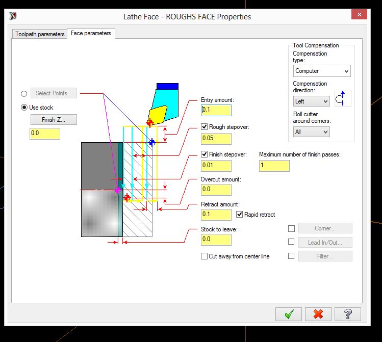
That worked for the home position but it still moves in X and Z at the same time.... Below is the code... I have tried ref points no go... G28 U0. G28 W0. N1 G0 T0101 G18 G99 M24 G97 S312 M03 G0 X2.45 Z.5 <------------------------------- This needs to be only Z move first then it can be X ... This can crash from the home position sometimes...---------------------------------------------------------> G50 S3500 G96 S200 Z.055 G1 X-.0625 F.01 G0 Z.155 X2.45 Z.01 G1 X-.0625 G0 Z.11 X2.45 Z0. G1 X-.0625 G0 Z.1 (ROUGHS O.D.) G0 X2.0506 Z.21 G1 Z.11 Z-3.6812 X2.192 Z-3.6105 G0 Z.21 X1.8512 G1 Z.11 Z-2.99 X1.8575 G3 X2.02 Z-3.0713 R.0812 G1 Z-3.9813 X2.1614 Z-3.9105 G0 Z.21 X1.6518 G1 Z.11 Z-2.99 X1.8575 G3 X1.8712 Z-2.9903 R.0812 G1 X2.0126 Z-2.9196 G0 Z.21 X1.4524 G1 Z.11 Z-2.99 X1.6718 X1.8133 Z-2.9193 G0 Z.21 X1.2531 G1 Z.11 Z-2.99 X1.4724 X1.6139 Z-2.9193 G0 Z.21 X1.0537 G1 Z.11 Z-2.99 X1.2731 X1.4145 Z-2.9193 G0 Z.21 X.8543 G1 Z.11 Z-.0021 X.9863 Z-.0681 G3 X1.0105 Z-.0973 R.0412 G1 Z-2.7543 G3 X1.0305 Z-2.7813 R.0412 G1 Z-2.99 X1.0737 X1.2151 Z-2.9193 (FINISHES O.D.) G50 S3600 G0 Z.1 X0. G1 Z0. X.7959 G3 X.8401 Z-.0092 R.0313 G1 X.9722 Z-.0752 G3 X.9905 Z-.0973 R.0312 G1 Z-2.7583 G3 X1.0105 Z-2.7813 R.0313 G1 Z-3. X1.8575 G3 X2. Z-3.0713 R.0713 G1 Z-3.95 X2.1414 Z-3.879 G97 S153 G28 U0. G28 W0. M01 (TOOL - 7 OFFSET - 7) (OD THREAD LEFT INSERT - NTC-3L10E) (MIYANO) (HEX_CAPSCREW_1.00-8UNCX3.00) (TURNS 1-8 THREADS) G28 U0. G28 W0. N7 G0 T0707 G18 G99 G97 S200 M03 G0 X1.19 Z.2281 G76 P010060 Q10 R0. G76 X.8512 Z-2.75 P694 Q214 R0. F.125 G28 U0. G28 W0. M05 M30 % -
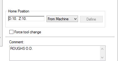
Hello, I have a MPLmaster post I am trying to make it post a G30 when I use home position user defined in X6 before and after tool change .. Also I need it not to post any Y axis code or a G54 ... How can I do this? Here is how it posts now G20 (TOOL - 1 OFFSET - 1) (OD ROUGH RIGHT - 80 DEG. INSERT - CNMG-432) (MIYANO) (HEX_CAPSCREW_1.00-8UNCX3.00) (ROUGHS FACE) G0 G54 X10. Y0. Z10. <------------------------------------------ Need this line to post only G30 X** Z** and no G54 or Y--------------------------------------------> N1 T0101 G18 G99 M24 G97 S312 M03 G0 X2.45 Z.5 G50 S3500 G96 S200 Z.055 G1 X-.0625 F.01 G0 Z.155 X2.45 Z.01 G1 X-.0625 G0 Z.11 X2.45 Z0. G1 X-.0625 G0 Z.1 (ROUGHS O.D.) X2.0506 Z.21 G1 Z.11 Z-3.6812 X2.192 Z-3.6105 G0 Z.21 X1.8512 G1 Z.11 Z-2.99 X1.8575 G3 X2.02 Z-3.0713 R.0812 G1 Z-3.9813 X2.1614 Z-3.9105 G0 Z.21 X1.6518 G1 Z.11 Z-2.99 X1.8575 G3 X1.8712 Z-2.9903 R.0812 G1 X2.0126 Z-2.9196 G0 Z.21 X1.4524 G1 Z.11 Z-2.99 X1.6718 X1.8133 Z-2.9193 G0 Z.21 X1.2531 G1 Z.11 Z-2.99 X1.4724 X1.6139 Z-2.9193 G0 Z.21 X1.0537 G1 Z.11 Z-2.99 X1.2731 X1.4145 Z-2.9193 G0 Z.21 X.8543 G1 Z.11 Z-.0021 X.9863 Z-.0681 G3 X1.0105 Z-.0973 R.0412 G1 Z-2.7543 G3 X1.0305 Z-2.7813 R.0412 G1 Z-2.99 X1.0737 X1.2151 Z-2.9193 (FINISHES O.D.) G50 S3600 G0 Z.1 X0. G1 Z0. X.7959 G3 X.8401 Z-.0092 R.0313 G1 X.9722 Z-.0752 G3 X.9905 Z-.0973 R.0312 G1 Z-2.7583 G3 X1.0105 Z-2.7813 R.0313 G1 Z-3. X1.8575 G3 X2. Z-3.0713 R.0713 G1 Z-3.95 X2.1414 Z-3.8793 G0 X5. G97 S76 G0 X10. Y0. Z10. <------------------------------------------------------------------- Need this to be G30 X** Z** only --------------------------------------------------> M01 (TOOL - 7 OFFSET - 7) (OD THREAD LEFT INSERT - NTC-3L10E) (MIYANO) (HEX_CAPSCREW_1.00-8UNCX3.00) (TURNS 1-8 THREADS) G0 G54 X10. Y0. Z10. N7 T0707 G18 G99 G97 S200 M03 G0 X1.19 Z.2281 G76 P010060 Q10 R0. G76 X.8512 Z-2.75 P694 Q214 R0. F.125 G0 X10. Y0. Z10. M05 M30 %

-
Hello, How do I make Mastercam always post a Z move first to approach the part and X only to exit? I can't get reference points to do this... It always post a X and Z on the same line which is a crash sometimes.. Is there a way to make it go to a certain home position in Z when approaching and the X when exit? I started with MPLmaster post... We have X6
-
Only post tool number on first M6
Darin replied to Darin's topic in Post Processor Development Forum
When I did that it takes out all of the tool numbers next to the M6.. I need the first M6 to have the tool number only.... -
Hello, How do I edit a MPmaster post to only post the tool # on the first M6? But I still want have it post the next tool like it is now.. So this is how it posts now.. N10 IF [VATOL EQ 5] N12 (SPINDLE TOOL CHECK) N11T5M6 <---------------------------------------------------------------------------First tool change is fine here ----------------------------------> N12S1500M03(SPINDLE TOOL JUMP) N13M09 N14(MAX - Z8.) N15(MIN - Z3.925) N16G00G17G90G15 H2M15B0.X-3.17Y9.9948S1500M03 N17G56H5Z8.T7 N18Z5.175 N19G94G01Z4.625F125. N59 IF [VATOL EQ 7] N61 (SPINDLE TOOL CHECK) N60T7M6 <-------------------------------------------------------------------------- This is the next tool it needs to be only M6 and for all the next tool changes -----------------------------------------> N61S500M03(SPINDLE TOOL JUMP) N62M08 N63(MAX - Z8.) N64(MIN - Z1.7115) N65G00G17G90G15 H2M16B300.X6.3652Y13.136S500M03 N66G56H7Z8.T6 Thanks
-
How to lock a post file to a HASP?
Darin replied to Darin's topic in Post Processor Development Forum
I don't have that .dll in my chooks directory.. How is this linked to the post file? And where do I edit the sim #'s? Do I edit the .dll file? Thanks -
Hello, Is there a way to lock a post to only work on a certain Mastercam HASP or sim #? It is for X6 Thanks
-
Ok I think i figured it out.. It was my plane it was set wrong... I set it to top WCS and right side both Tool Plane and Construction plane and now I get the correct code when I change the tool axis length box. But it is posting a G19 instead of a G17... Is this right? N100 G19 G20 G90 G40 G80 G64 G49 G0 M05 N110 G8 P1 N120 G90 M05 Z0 N130 G52 X0. Y0. Z0. N140 T5 M6 ( RIGHT ANGLE HEAD ) ( RIGHT ANGLE HEAD OPPERATION LAST OPP ) ( INITIAL BUILD ) ( 1ST SET - HELIX BORES THE .030 & .035, DIA HOLES WITH 90 DEG HEAD ) N150 G0 G90 X7.175 Y-1. C0. N160 S3000 M3 N170 G43 H5 Z2.8178 N180 G1 X7.15 F40. N190 G41 D5 Z2.8028 F15. N200 Z2.7878 N210 G3 X7.149 Z2.8478 J0. K.03 N220 X7.148 Z2.7878 J0. K-.03 N230 X7.147 Z2.8478 J0. K.03 N240 X7.146 Z2.7878 J0. K-.03 N250 X7.145 Z2.8478 J0. K.03 N260 X7.144 Z2.7878 J0. K-.03 N270 X7.143 Z2.8478 J0. K.03 N280 X7.142 Z2.7878 J0. K-.03 N290 X7.141 Z2.8478 J0. K.03
-
It says this in the MRrouter post but I don't get any change in the code when I set these up... Shouldn't I see a change in the code somewhere for it compensating for the center of the head to the tip of the tool somehwere in the code? # - Modified position shifting for aggregates - # If use_oal is set to yes$, XYZ values are shifted based upon tools overall length value and aggregates "Tool Axis Length" # value (if defined). The aggregates "Tool Axis Length" value is the fixed "gauge length" from pivot point to collet face. # Setting this value in the aggregate definition allows the end user to set the tools overall length value from collet face # to tool tip rather than calculating from pivot point to tool tip every time the tool is changed. # set_g43_vert controls how the aggregate tool is touched off on the machine (ignored when use_oal = no): # 0 = Set in horizontal position (Centerline of tool) # 1 = Set in vertical position (Tool tip) # 2 = Set in horizontal position if fixed right angle aggregate, vertical position if compound angle aggregate - # post determines based upon aggregate type set in aggregate component.
-
I started with a MRrouter X6 post in Mastercam.. I have tried changing the area in the post where it says set height height offset with tool in vertical postion and #Override Work Offset with Aggregate Offset Register Tried both of those and it doesn't chnge the code.. ug4$ : 1 #Debug output with the tilde '~'. #A value greater the zero applies the variable formatting with #debug output (default is typically FS 1 but not a guarantee). #A value of zero gets the value directly with NO formatting. linktolvar$ : 0 #Associate X tolerance variables to V9- variable? linkplnvar$ : 0 #Associate X plane specific variables to V9- variable? skp_lead_flgs$ : 0 #Do NOT use v9 style contour flags bdrl_use_lead$ : no$ #Output the lead drill as drill position w/block drill use_ra_offs : yes$ #Override Work Offset with Aggregate Offset Register use_oal : yes$ #Scale coordinates to tool length with Aggregates <--------------------------- Put this to yes no change in code ----------------------------------> use_g8 : yes$ #Use G8 P1 for Fast corner (adv preview) function? use_dc : no$ #Output codes to raise and lower dust cover? use_tl_select : yes$ #Use tool code string select for drill block? use_hd_select : yes$ #Use tool code string select for multi-heads? set_g43_vert : 0 #Aggregate - set height offset register with tool in vertical position? <--------------------- Changed this line to 0,1,2 no change---------------------> # 0 = No, set in horizontal position # 1 = Yes, set in vertical position # 2 = Set in horizontal if right angle aggregate, vertical if tilting aggregate dual_table : no$ #Set to yes to enable misc integer option use_brush_ht : no$ get_1004$ : 1 #Find gcode 1004 with getnextop? rpd_typ_v7$ : 0 #Use Version 7 style contour flags/processing? strtool_v7$ : 2 #Use Version 7+ toolname? tlchng_aft$ : 2 #Delay call to toolchange until move line cant_tlchng$ : 1 #Ignore cantext entry on move with tlchng_aft newglobal$ : 1 #Error checking for global variables getnextop$ : 1 #Build the next variable table tooltable$ : 3 #Pre-read, call the pwrtt postblock rotaxtyp$ : 999 #Rotary Axis Override cutpos2$ : m_one #Disable cutpos2 if not 4 axis, saves time
-
Tried both nothing changes the output of the code...
-
Ok no matter what I put in the Tool Axis Length box I get no change in the G code... The .025 hole is located at X.150 Y-1.0 Z2.8178 normal for top veiw in Mastercam.. Below is the code it creates.. Why isn't the Z changing when I chnge the Tool Axis Length box dimension? What am I doing wrong? For some reason it posts out X is now Y and Y is now Z but it has also another Z that would be normal if there is no right head... Isn't also supposed to be G19 instead of G17? O0042 (15-422803-00 RB RIGHT ANGLE HEAD) (RIGHT ANGLE HEAD) (RIGHT ANGLE HEAD OPPERATION LAST OPP) (INITIAL BUILD) (PROGRAM - 15-422803-00 RB RIGHT ANGLE HEAD.NC) (DATE - JAN-30-2013) (TIME - 3:57 PM) (T3 - 180.00 / 90.00 - STATION # - H3 - D3 - D0.0200") N100 G00 G17 G20 G40 G80 G90 N110 G91 G28 Z0. N120 T3 M06 (180.00 / 90.00 - STATION #) N130 (MAX - Z.175) N140 (MIN - Z-.025) N150 G00 G17 G90 G54 X-1. Y2.8178 S3000 M03 N160 G43 H3 Z.175 N170 G94 G01 Z-.025 F5. N180 G00 Z.175 N190 M05 N200 G91 G28 Z0. N210 G28 Y0. N220 G90 N230 M30
-
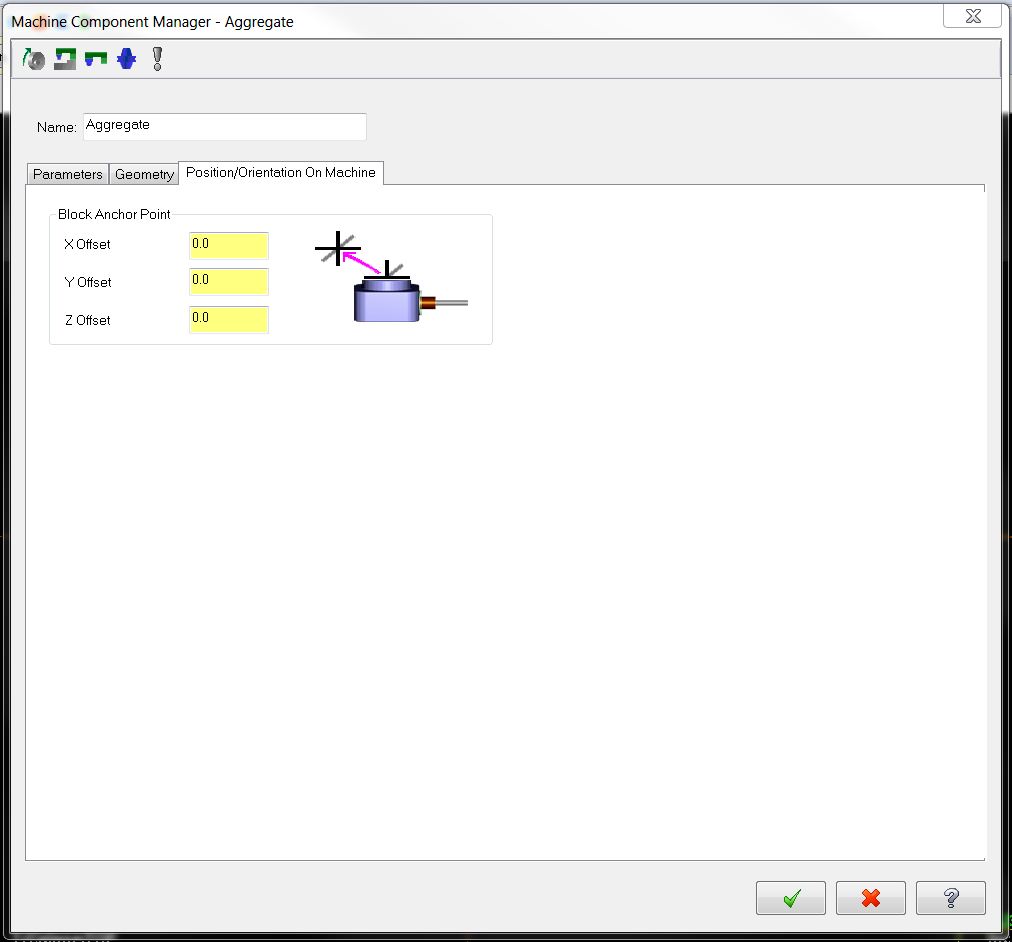
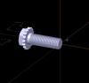
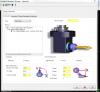
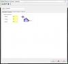
Great ... So is the tool length controlled here? (See picture) In the Machine Component Manager- Aggregate? So I need to know the center line of the head and from there to tip of tool? Pu it in the Tool Axis Length box? Does the machine view angle have to be 90 or 180? I have seen both.. There is a pic of the 90 deg head also..
-
Hello, We have a part that is going to need a right angled head on our Haas.. I know how to program it in Mastercam using a Router post and it just routates the plane with aG17.... but how does it know the length of the tool or where to set it? The X0,Y0, is center of the part (See picture) and the Z0 is top of part... Do I just touch the tool from the top of the part and move down half the dia of the tool? But how does it know the length from the center of the right angled head to the tip of the tool? Make sense? Thanks
-
Need to post a M15 or M16 before B move
Darin replied to Darin's topic in Post Processor Development Forum
Thanks... That worked but only if I have signed direction absolute checked in the machine definition manager... Thanks -
Where is the program # controled in Mpmaster?
Darin replied to Darin's topic in Post Processor Development Forum
That was it thanks..... -
Hello, I need to add some apostrophes around the program number in the post for a Bridgeport machine.. Where is the below code controlled in the a Mpmaster post? O2931 '15-354293-00RA OP1' <---------------------------------Need it to post apostrophes around the program # like this'O2931' -------------------------> 'PROGRAM - 15-354293-00RA OP1.NC' 'DATE - JAN-25-2013' 'TIME - 3:11 PM' 'T1 - 2.5" FACE MILL - H1 - D1 - D2.5000"' G00 G17 G20 G40 G80 G90 G91 'COMPENSATION TYPE - OFF' T1 M06 '2.5" FACE MILL' 'MAX - Z4.' 'MIN - Z0.' G00 G17 G90 X-1.375 Y-.625 S3200 M03 H1 Z4. Z.1 G01 Z0. F20. X0. X2.5 X3.875 G00 Z4. M05 G91 M25 G90 Thanks
-
Need to post a M15 or M16 before B move
Darin replied to Darin's topic in Post Processor Development Forum
I tried this and it still doesn't post any M code any where. I even tried it on a un-edited Mpmaster post and it doesn't post either.. It is controlled in the machine def or control somewhere? Thanks -
How get rid of comments on the top in post?
Darin replied to Darin's topic in Post Processor Development Forum
Great thanks guys... That worked perfect..