Thoob
-
Posts
579 -
Joined
-
Last visited
Content Type
Profiles
Forums
Downloads
Store
eMastercam Wiki
Blogs
Gallery
Events
Everything posted by Thoob
-
Ok. Its a 3 axis VMC. Attached on the original post.
-
Hi guys, I'm in a real bind right now. I was given this part from upstairs and told we have to make 4 of them asap. The problem is I am not knowledged enough to know where to start to program it. Can you guys maybe give some advice on what toolpaths I should use? The part has the outside profile cut from a waterjet but there is 1/8" extra material left at the places shown in the picture(red entities). Its 3" thick and material is QT100. I attached the model and also the waterjet profile. SAFETY DOG OPTION 2.MCX-6 W2013163-2001 SAFETY DOGS-RH WATERJET.MCX-6

-
Thank you. I got it.
-
Ok, so I would have to draw geometry for the stock then? I assume pick multiple machining regions. Select the stock for machining regions and the finished part for avoidance regions?
-
Hi, I am looking to machine the outside of this part and as you can see I have the stock shown in red. I want to use a toolpath like the one in this video Here is the part http://i1254.photobucket.com/albums/hh602/ThoobHertz/dynamiccore_zpsadffd821.jpg I was told it is dynamic core and I have selected that in X6 however it wants to machine the inside. So basically I would just like to get a quick rundown of what settings to choose to get the toolpath correct. I am mostly concerned at how Mastercam reads the stock.
-
Ahhh, that was it. Thanks a lot fellas.
-
Ya Paris thats what I meant when I said I didn't seem to have a problem offsetting one way. I can't make it go the other way though. Not sure why or what I may be doing wrong. My offset direction tab is greyed out. It won't let me change direction.
-
Hey guys, just wondering if there is an easy way to offset a surface like the example I have below. See picture. The slot is 3/4" wide and tapers up at 45 degrees. I need to make 3 different sizes but maintaining the rest of the part. So in other words I need one with a 1" slot, a 1.25" slot, and a 1.5" slot. I seem to be able to offset it smaller but I don't know how to make it bigger.

-
Hey guys, I'm looking for a good dust cover to enclose my computer. It is right on the floor and attracts quite a lot of dust and metal particles. I'm talking about having to blow it out every 2-3 weeks. I had some Shop shields from www.computerdust.com and they claimed they would work and never overheat. Well they are partially wrong. The heat got pretty far up on the scale and while it wasn't enough to shut the computer down, it was above where I wanted it to be. Besides I found they got clogged with dust and still let it in the computer faster than they should have. So, I am looking at 1 of 3 things. To build myself some sort of container with vents.(Don't really want to go this route), buy an enclosure(if some of you can suggest), or buy a case that has a filter system directly on the fan holes. Any ideas?
-
If this was me, and there was no word of "not using coolant" in the quote as you mention, I would be upping the price based on that alone. You don't like it? Take your parts back. I think its stupid to take a job that you will lose money on. Not even worth the time to talk to customers like that. To me that is a key factor and should have been mentioned up front first thing. As for machining dry like that with such a small hole, I say good luck. That will not be an easy feat.
-
Ya I was asking of the ram drive cause of the memory usage you were using. I thought if you had a ram drive, that would explain your high memory use. Those must be some pretty intensive models to get that much memory use.
-
I gotta ask, are you using a ramdrive? If you are, you can add that size to your memory usage. Example if you have a 10GB ram drive and Mcam is using 5GB, your task manager will show 15GB being used. That is crazy to be using that much memory, lol. I'm the same as Ninja, I never see that kind of memory use.
-
-
Ya thats fine Jay.
-
I have Jay working with me on getting it right. I agree that the flowline toolpath works the best as the step down is small so the cutter being engaged that far is ok. Its that first initial cut that is the problem. I was thinking I might just drive that height with multiple passes until I have most of that area taken out, then finish with the flowline? Jay I replied to your email yesterday afternoon.
-
Sent you a PM
-
I would like that. Thank you.
-
Ya re read it. Its the same. lol 5/8" diameter inserts = 5/16 radius. Part is 17/32 radius = 1-1/16 diameter
-
^^^^How does he do it? lol
-
Its just 44W plate, Mild Steel. I am testing different methods as you guys suggested. I will let you know how I do. I really appreciate the responses. Thank you. Just one thing though, how do you control the lead in and out so it doesn't gouge the part with flowline?
-
If I use a 2D toolpath with multipass, how will that get rid of most of the material? Its a 17/32 Radius and the cutter is only 5/16 radius. It would not take out near the top and bottom of the rad, only the middle. Not so familiar with these types of surface toolpaths. I'd say I'm a little green ion that area. Thanks ChipMaker, I will try to make the edge a drive surface.
-
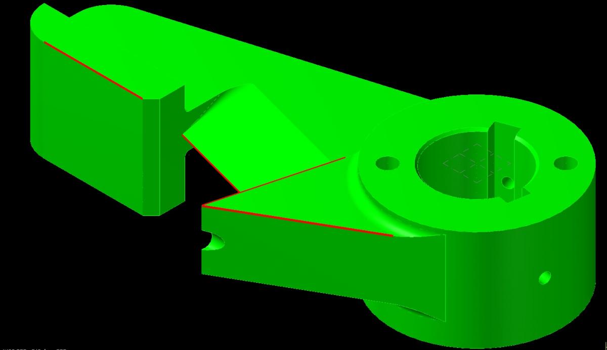
I attached a picture for better visualization.
-
Hey guys, I have a part I need to undercut. Picture a pulley, thats the kind of undercut it is, however it isn't round so I cannot turn it on the lathe. The problem is I don't know how to put a rough cycle to it to take the material out radially. The "surface contour" I'm using wants to take a lot radially which I can't do cause 1, the tool can't handle it and 2, the part is not that rigid to accept such a large cut. What toolpath would I use to remove that material out? The tool is a slotmill 5.08" diameter and 5/8" diameter inserts. The part undercut is 17/32 full radius.
-
Ok. See that is where I was different. I don't draw the MD like that. I actually drew the md and then added a number in the overcut allowance. I did it with an endmill as you suggested vs the way I did it, and its funny the code is indeed different. Does the allowance overcut actually work different than how I think it does? The way I drew the 2 was the 2nd side like you said, then the first side by drawing the pipe face(md) 1.175" and then putting an overcut of .0665. This technically should equal the same 1.175+.0665+.0665 = 1.308 but the code it outputs is different. See picture.
-
I still don't fully understand what you are saying. The tool is one threadform. It does a range of 12-24 TPI. I know the NPT in question is 11.5 TPI and I have adjusted the depth to compensate for it. I double checked the tool and it is drawn to a point (my mistake from my earlier post) So from the center of the tool to the "tip" of the tool is measuring .427" The other issue here is that I cut a straight thread shortly after I did the NPT and the offset only needed to be adjusted .006. So this tells me the tool is defined properly. I am wondering, do I have a mistake in the thread depth? What is the Single Depth for a 1"-11.5 NPT? EDIT - I assumed it was .059. This apparently is not correct according to a few charts I looked at. Assume we use your number from Column 2 which says 1.315 and that the pipe face (md) is 1.1725 (this is correct for this 1" NPT thread), then that makes my single depth .071. If I minus .059 from that, it gives me .012 difference. This is ok however I was originally .039 out so this still leaves me with .027 of unknown. lol. This is ridiculous.