tsaladyga
-
Posts
133 -
Joined
-
Last visited
Content Type
Profiles
Forums
Downloads
Store
eMastercam Wiki
Blogs
Gallery
Events
Everything posted by tsaladyga
-
Hi guys, Was wondering if anyone knew how to split a model in half in order to machine part of it. I have attached the file. We have an Okuma VTM that the boss does NOT want to use "C" axis for surfacing the volute. Don't ask why cause I don't get it either. But what he wants to do is position the part at "C0" machine half the volute, then rotate to "C180" and machine the rest. I have already roughed it out on a mill, just need to finish with a 2" ball. I figured the easiest way would be to cut it in half, rotate it the way I want it, then just edit the rotations. Thanks, Todd DR-10028922_TEST.MCX-7
-
Thanks Peter, I tried it but no go.
-
Can someone show me how to make a pfzout line in a post subtract a misc value? Here is the line I want to modify: pbld, pn, *scclgcode, pfxout, pfzout, *stepcc, *grvspcc, *clearcc, *mr4$, feed, *mr5$, pe Basically I am programming a grooving cycle with back offsets in an Okuma VTM, but the shop wants to see the back groove number as what is on the print. Soooo, This is what I need. If it is a .500 groove at z-1., then they want to see, G00 Z-1. G73 X5.00 Z-.5 K.250 D.3 L.6 E4 F.003 T94 In order to output the code, I want to have the pfzout show " pfzout minus misc. real value 9(I will enter the width of the insert there) Any takers? Thanks, Todd
-
Ok Guys, Here's a stumper for me. I have this post I am working on for our Toshiba Tue VTL's. I am trying to create custom probe routines. One routine we do is take probe points along the face of a part and average out the stock. We do this with Cast Iron Parts that have surfaces that don't get machined. This way we are not too heavy on one side than another. Anyways, This is a sample of the Routine: N12 G0G59X41.C30. N13 Z.875 N14 G65P9831K2 N15 G65P9810Z-.735F100. N16 G65P9811Z-1.235 N17 #596=#138<-------- this is the "count up". The #596 start number is specified in the custom parameters box in custom drill cycle. Then the post counts up the number by the points selected N18 G65P9810Z.875 N19 G0C90. N20 G65P9810Z-.735 N21 G65P9811Z-1.235 N22 #597=#138<-------this is the "count up". #597 N23 G65P9810Z.875 N24 G0C150. N25 G65P9810Z-.735 N26 G65P9811Z-1.235 N27 #598=#138<--------this is the "count up".#598 N28 G65P9810Z.875 N29 G0C210. N30 G65P9810Z-.735 N31 G65P9811Z-1.235 N32 #599=#138<---------this is the "count up".#599 N33 G65P9810Z.875 N34 G0C270. N35 G65P9810Z-.735 N36 G65P9811Z-1.235 N37 #600=#138<---------this is the "count up".#600 N38 G65P9810Z.875 N39 G0C330. N40 G65P9810Z-.735 N41 G65P9811Z-1.235 N42 #601=#138<---------this is the "count up".#601 N43 G65P9810Z.875 N44 #602=ABS[[#596+#597+#598+#599+#600+#601]/6]<------this is where it adds the variables then divides by the number of points(which I input in the custom para. area) N45 IF[#602GT1.235]GOTO5000 N46 IF[#602LT1.235]GOTO5100 N47 IF[#602EQ1.235]GOTO5200 N5000 #700=[#602-1.235] N49 #5322=[#5322-#700] N50 GOTO5200 N5100 #700=[1.235-#602] N52 #5322=[#5322+#700] N53 GOTO5200 N5200 N55 #5222=#5322 N56 #5242=#5322 N57 #5262=#5322 N58 #5302=#5322 N59 #500=0 N60 G0Z5. I was able to get the count up feature to work but now I have to use those values in determining the Average. I can't make it permanent because the number of probe points is going to change from job to job. Soo my question is, how do I create a formula for the line above which I will highlight in yellow. Any help would be greatly appreciated guys. Thanks, Todd
-
mi10$ Program Stop at end of toolpath
tsaladyga replied to tsaladyga's topic in Post Processor Development Forum
Thanks Craig! That was the ticket! -
Pulling Manufaturers data from tool
tsaladyga replied to Bocho's topic in Post Processor Development Forum
Thanks Rocheey1! I was wondering how to output the tool code! We use the Tool Code window fro barcodes so the guys can scan the barcode to get an insert out of the vending machine. -
Can anyone show me how to make the mi10$ give a M00 or M01 at the end of a toolpath and not at the beginning? Right now it says: "M00 Before Operation [0=No,1=Yes]" I would like it to be: "M00 After Operation [0=No,1=Yes]" We do a lot of program stops to check tool length, insert checks etc. and It is kind of a pain to remember that if you want to output M00, you have to go into the "next" toolpath to turn it on instead of just doing it in the current one. My post shows this: It doesn't have the "plast" line in it. if posttype$ = two, pl_retract else, pm_retract if mi10$ = 0, n$, sm01, e$ else, n$, sm00, e$ Thanks guys, Todd
-
Why doesn't X7 show the coolant on/off
tsaladyga replied to Trapper Paul's topic in Industrial Forum
I never liked it because of the fact it didn't work for X style. But I do think maybe it would be a great idea to put it back in under display options -
Ok Cnc Software Geeks: Mach Sim Lathe needs
tsaladyga replied to tsaladyga's topic in Industrial Forum
I still say that there should be some attention to Lathe Sim. We have 15 VTL's with live tooling at our company. To say Lathe Sim isn't needed is just wrong. If anyone works for a company with more than one programmer then they would know there are different levels of skills. Those that know, and those that don't. Unfortunately the company I work for has a few "newbies" in the programming dept and I can't possibly stand over them all at the same time. You could argue a lifetime with me about Mill Turn, but unless it's free, then it is just another lame attempt from CNC software to charge their customers for something that should have been done years ago for free. I believe that is what Maintenance fees are for. Lathe SIm would give those of us who still operate 2 axis turret style lathes some sort of verification. I for one can say we make some pretty complicated parts on our machines that would certainly benefit from Simulation. We are always dealing with travel issues and tool length issues that would be invaluable in a Sim.(Because then we are not wasting machine time looking for tooling, figuring out pad heights, trying to adjust tool lengths, etc.) As far as collecting data from the Machine Builders, Cnc could always ask their Customers for feedback with reference to machine definitions. We all have books(or most of us) that show the dimensions of our machines. I certainly would not be against helping CNC out by providing details of our equipment. I have tried to approach my company on the subject of purchasing Vericut, but they said it is too expensive to justify buying it. I agree to an extent. I think if Mastercam can come with Machine Simulation for 3 4 and 5 axis mills, how can it really be that hard to create 2 axis turning Machine Simulation.? I have been using Mastercam since version 4(yes that is 4 not X4 ) I am and have always been a supporter of Mastercam, however, if there is one thing that really drives me nuts, it's that Cnc seems to come out with new versions all the time, but it seems the same problems are in each new version without ever really getting fixed. I would rather see an X5 for 5 years that gets fixed then an X7 that still doesn't have screen capture, that still crashes, that still doesn't have a full lathe tool library(how do we have insert milling cutters, but not insert drill tools?) Any ways, that's my rant. -
Teejay, Do you happen to know Ivan's e-mail? Never Mind, I found it.
-
What we have are 2 1060e V6 machines with the Palletech high rise system both with MAZATROL FUSION 640M control. Is that Matrix? Not sure. I will e-mail Ivan.
-
Thanks TEEJAY, I will try the Multi Axis(G43.4) Yes it appears to be an In house post. Initially written in 04 and modified for this company in 07. Unfortunately it is set up as a horizontal and the machine is vertical, plus the axis are all pointing the wrong way(not sure why) I am trying to create a new machine def as vertical and develop the parameters so the programmers can use it effectively. So any help I can get is greatly appreciated. Todd
-
We have a job that needs a 2.5 " groove 1.8 deep approximately on an OD. On our Mazak Integrex 1060 e. I am trying to run a tool path using C axis contour, but when it gets to 360 degrees, it wants to rapid back to zero then count up again. Is there a way to plunge a 1.5" feed mill to depth using some sort of ramp method then finish with a ball end mill? Thanks, Todd
-
oops
-
X7 SPEEDS AND FEEDS CALCULATOR STILL BROKEN?
tsaladyga replied to neurosis's topic in Industrial Forum
I am having the same issues when I create a custom tool. Almost every time I go to save the tool it crashes. Luckily I don't lose it, but it is annoying -
Ahhh! Thanks Scott! Right there in front of me.
-
Is there a way to create my own LIC file for lathe toolholders? Thanks, Todd
-
Ok Cnc Software Geeks: Mach Sim Lathe needs
tsaladyga replied to tsaladyga's topic in Industrial Forum
2D Lathe is great for Travel limits and crash moves, Backplot doesn't show those. The company I am with now puts all the accountability on the programmers(It sucks and I am currently changing the way they do things), but we a have 2 new programmers that are just starting out, even though 2D lathe is simple, it isn't for the newbies and I thought a 2D Mach Sim would and could certainly come in handy. I think Vericut is way to complex for what we need, Which is why I can't understand why Cnc software never made a simple 2D lathe (horizontal and vertical) Sim file. -
I am looking to get a Mach Sim for a 2 axis VTL. Anybody from Mastercam land have any ideas why after 7 versions of X we still don't have Mach Sim files for turning? Sure would be nice to see travel limits or crash moves in those machines as well. Especially since our business is about 75% turning and we have about 35 Turning centers. Maybe one of the Gurus can break from their golf game to create one? Any ideas would be totally appreciated. Thanks guys Todd
-
I don't understand why after all these X versions Mastercam hasn't come up with a Lathe for Mach Sim. It really sucks to have to pay another company 50,000 for a stupid verification software when Mastercam should be able to do it with in the software. As far as where does the part know where it is? If you're using a lathe such as I want to, the part is gonna be at the same place everytime correct? We have Z zero at the face of the chuck and if you do it that way, all the travel comes from the gauge line. Thanks guys, I will mull this over and see if I can come up with a solution. I think it's time to get the boys from CNC software to realize that turning is as important as everything else. Maybe they can come up with a standard 2 axis horizontal and Vertical Mach Sim.
-
I thought there was a way to set up a machine definition with travel limits so that when you back plot, if a tool is going to over travel, Mastercam lets you know? Can anyone help please? Thanks, Todd
-
Nevermind, Duh, I got it! Man I hate brain fa*ts! I Forgot it was in the Config menu. Thanks all
-
Does anyone know how to remove the arc center points from the screen? I created curves on all edges of a solid for wire frame and now I have a dust storm of center-points all over the screen. Is there a way of blanking them so the screen doesn't look so dirty? Thanks guys

-
Ok. I have this: if tapflg , [ pbld, pn, "M845", pe tapflg = 0 ] but when I post it isn't coming out. This is my tap cycle: pdrlcommonb if recallflg | drlcyc = 0, [ #RH/LH based on spindle direction if rigid_tap, [ pbld, pn, *speed, sm05, pe #Rigid Tapping pbld, pn, *sm29, pe #Rigid Tapping ] if use_pitch = 0, [ pcan1, pbld, pn, *sgdrlref, *sgdrill, pdrlxyz, pdepth, paout, pcout, prdrlout, [if peck1$, *peck1$], *feed, strcantext, pe tapflg = 1 ] else, [ if met_tool$, pitch = n_tap_thds$ # Tap pitch (mm per thread) else, [ if metric_vals, pitch = 1/n_tap_thds$/25.4 # Tap pitch (inches per thread) else, pitch = 1/n_tap_thds$ # Tap pitch (inches per thread) ] pcan1, pbld, pn, *sgdrlref, *sgdrill, pdrlxyz, pdepth, paout, pcout, prdrlout, [if peck1$, *peck1$], *pitch, !feed, strcantext, pe ] drlcyc = 1 recallflg = 0 ] else, [ pcan1, pbld, pn, pdrlxyz, pdepth, paout, pcout, prdrlout, !feed, strcantext, pe ] pcom_movea I have set rigid tapping on. I get the M843 at the beginning of the cycle, just not the M845 at the end. N25 T16 (3/4-10 NC BOTTOM TAP) N30 M06 N35 G57 H901 N40 G90 G00 B180. N45 G00 X-2.438 Y7.5 N50 G173 W-19.55 N55 G43 H16 Z.25 M08 N60 G95 N65 S200 M05 N70 M843<--------------------------- outputs this ok. N75 G99 G84 Z-1.1 R.25 F.1 N80 X-4.813 Y8.063 N85 X-6.875 Y6.375 N90 X-7.313 Y3.719 N95 X-10.125 Y3.5 N100 X-12.688 Y2.594 N105 X-13.5 Y0. N110 X-12.688 Y-2.594 N115 X-10.125 Y-3.5 N120 X-7.313 Y-3.719 N125 X-6.875 Y-6.375 N130 X-4.813 Y-8.063 N135 X-2.438 Y-7.5 N140 X2.438 N145 X4.938 Y-8.156 N150 X7.094 Y-6.438 N155 X7.359 Y-3.625 N160 X9.563 Y-1.531 N165 Y1.531 N170 X7.359 Y3.625 N175 X7.094 Y6.438 N180 X4.938 Y8.156 N185 X2.438 Y7.5 N190 G80 <------------ ----------------------------------missing M845 N195 G73 Z78.74 W0. M09 Help please? Thanks, Todd
-
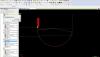
Ok, i have done a screen shot of the toolpath after I choose change at point and toggle Manual antry. See the Big arc? That isn't supposed to be there. It is supposed to turn the chamfer, then turn the first dia. and insert a secondary offset to control the taper, then radius and face and son on. If I toggle off the Change at point it is fine.