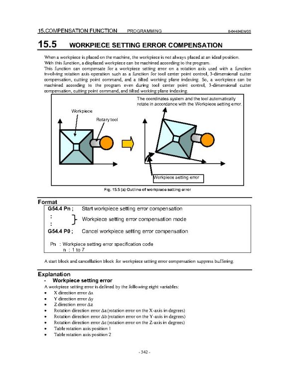
motor-vater
-
Posts
379 -
Joined
-
Last visited
-
Days Won
4
Content Type
Profiles
Forums
Downloads
Store
eMastercam Wiki
Blogs
Gallery
Events
Everything posted by motor-vater
-
was getting a few depending on format. I should have wrote them down, so I'm just going off memory here for now. Originally it was illegal G68 command, on the G69, then I tried moving the G54.4 above the G49/G69 and started getting an illegal WSEC error it became obvious The G54.4 P0 does not want to be before the G49/G69. So moved that back and tried some other stuff but oddly enough removing the G05 P0 gets rid of the illegal G68 alarm, but why the illegal g68 alarm on a G05 P0 has me scratching my head. Ill post some shorter cycles tomorrow for more detailed info, But I had that spindle shut down for 4 hours today playing around, so I gotta be mindful of our customers. Lol While I got you on the hook James I have a question about the error values in the Wrk setting errors. Try to imagine my part be a U shape, in the machine it is an orientation where rotating around the b axis would turn my U into a C. Now when I first load, I am probing the center of the U for my G54. Thats where the part is programmed from. But Then I must rotate my B axis to get the legs of the U even...... Still with me? Today it took -0.101 deg on the B to get there, So I enter that error into the b on my error page. My question is when I come down and reprobe the center of that U it has Moved/Followed and is now .120 shifted in my X. So do I enter that into the x on the error page aswell, or does it just know to follow cause of the b error adjustment. I ask cause I almost wonder if I should just find and set my rotational error first, then just probe the Center of my U with the B axis at -.101 to the G54 and be done with it? But as I am typing I am thinking probably not a good idea, but How do I find the theoretical perfect position of the part as it was programmed when it has to be skewed to get to that position. Probably why some would Use COR for this I think. Then all you are measuring are errors, Sorry Long winded I am and I hate to take advantage of your kindness, But Lunch on me sometime when we cross paths... Edit: Just dawned on me I can steal the theoretical perfect numbers outta mastercam, Just create a plane at COR and get the values of my Origin point and enter those into my G54. Then that should make my b and x error values valid. Maybe. LOL If that works I would never need to reprobe my G54 and could spend all my energy on the errors...
-
Ran some test cuts today, found a few more format errors. When the post outputs a B0, C0 cut it does not use 68.2 So the G54.4 came after the B0. C0, call and did not move the axis'. Was ezily corrected by adding a B0. C0. after the g54.4. I got a list going for when I reach out to the boys at postabilitly, I know they will get it all dialed. But the one Format error that is killing me is the look ahead, no matter what I do I get some kind of alarm with it. It did not like G05.1 p1 at all alarmed out immediately. Usually the old post always used G05 p10000, So I went with that and it works but always alarms out at the end of a toolpath when trying to turn it off. G05 P0. I tried moving it around and it always alarms no matter where its at. tried canceling the g54.4 first, didn't like it, tried after, no good tried the way James showed above, nothing Without G54.4 my post would output like this, and never had problems G0 Z4. G49 G69 G05 P0 M9 M5 M81 M69 M11 G0 G17 G40 G80 G90 G98 G91 G28 Z0 G28 X0 Y0 G90 M01 New post wants to do this and it alarms out Z-7.1333 M05 G49 G05 P0 M9 G69 G54.4 P0 G53 Z0. G91 G28 Z0. M11 M69 G28 B0. C0. M01 Ideas? Thanks Everybody for getting me this far
-
Success Update! Seem to be going in the right direction with the format difference, I am now able to get the G54.4 to run with the G68.2, Thank you James. Now I will have to make some test cuts to really figure out how the errors work but So far the Code I posted, a simple square pocket, calls for a rotation of C90, B5 deg and then linear X and Y moves. But as you will see in the video Adding 1 deg of error to the b on the Work Setting Error, moves the axis' to C78.715 and B5.099 and my liner moves are now traveling along both axis' simultaneously. This is a good thing, the machine is now thinking for itself and correcting for the error. I will have a few last questions after the excitement wears off but wanted to update those that have contributed. https://youtu.be/iEKy04TZEAI
-
This Helps immensely, Thanks James. Ill do some experimenting tomorrow.
-
Link to a quick video showing the set up screens. I am thinking the Last page I get into is where I stick the error Values? https://youtube.com/shorts/0R59J2wZnjI
-
Pretty sure, I agree with you, I think the G54.4 and G54.4 came Standard with the A5 control. Maybe the 68.2 and 43.4 were options the had to pay extra for. IDK I use 68.2 or G43.4 for everything that gets posted for those machines and have never Had a problem, Can move X,Y,Z and C and where I want with no Problems. Its this Dam B axis That does not want to be lied to..
-
yes both, probably a format error there too. I got a illegal command G68.2 error when trying G54.2, PS5462 to be exact
-
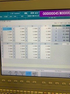
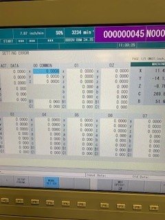
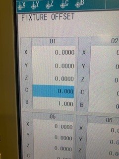
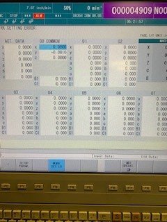
Lol! Well I have heard Rumors that our old Mam 72 might be looking shinny new here real soon, but I would hate to try to stuff this part into that thing, it takes up the entire work area of the 5000's As to the work offsets, I think I may have added a confusing statement. I am talking about 2 different screens I see past my regular work offsets. I have Work Offsets, then Fixture offset screen, then deeper in the Work setting error screen... So Im trying to figure out which of the 2 secondary offset screens I use? The pictures I included were of the fixture offsets screen, then the Work Set ER, screen. I'll try to make a better picture set or video tomorrow
-
I definitely appreciate you chiming in on this James. I know from past threads u have experience with G54.4. I will give it a shot. What about a G49 or will the one that output before the tool change do? Once I get working code I am sure Postability will get it to output correctly. Also If you dont mind sharing a little more, I would love to know which screen I should be using, Fixture offset or the Work setting error screen? Thanks for all willing to contribute
-
I definitely feel you, And I read it the same way, problem is I need the rotation around the Y (b or B) in order to be able to even get the part in the correct orientation/ relationship to the spindle. Basically if I indicate and shim the part in the fixture on every part, the features are all perfect to each other when cut. The problem is in setting up the casting. We can make good parts with the program, it just takes 45 minutes to set each one up and I am trying to stream line the process, by hopefully using the functionality of the control.
-


-
Thank for the response I have 2 pages, probably doing it wrong no doubt, I have a fixture offset page, and a work setting error page, I have tried entering values into both with no good result from either. Which on should I be using? The Fanuc Book described using a,b,c So I assumed this page was more what I was looking for.
-
So I have questions regarding G54.4 with the use of G68.2. More about how to set up the fixture error than anything else. I have never used this feature in all my years and the one time I need it, its laughing at me. I have read the Mori Book, the Fanuc Book, and talked to the Mori Applications Engineer, Aswell as read every thread related to it on the forum, and sadly I still am struggling Things I know · Fanuc 31iA5 on Mori NMV5000, needing to cheat my B axis (around Y) to deal with some casting indifferences. · Feature is equipped on control (not sure about parameters configured) · I get a PS0437 Alarm when I try to add values to the b, c, B, C. But seems to only happen with g68.2, G43.4 seems to work but does not go to the right area of the part · I have a Postability post that has a switch and will output G43.4 Pn Questions I have · Should I post from COR ( I don’t wanna! ) · But if I do use and use probing to find error form COR, I use those values in fixture error? · When trying to cheat my B axis do I put my error in b, or B1 If I post from my probed datum points, do I · Leave G54 set to COR and then put the probed difference in to fixture error? X0, Y-6.2048 Z 12.6935 · Or do I set G54 to the theoretical probed perfect point and use errors as slight adjustments What I am trying to accomplish I need to rotate about the Y so that I can bring 2 features into alignment before cutting, because the back cast surface that supports the part in the fixture is not true to the datum targets its either that or shim and indicate every part into the fixture. It’s a TINY adjustment sometimes a .01 adjustment to the B sometimes a half degree. The program is all 3+2 but also uses B axis to cut a feature that lays at 5 deg. , but requires the C to move 270 deg. I feel like the machine should be able to do this according to the Mori guy, its just a mater of getting it programmed right, posted right, and have the correct error values. There will be more info to follow but ultimately I don’t want to overwhelm the first post. Here is an example of how my post outputs (HOME POSITION COORDINATES) (X0.= CENTER OF CASTING DATUM -B- APROX 0.0 FROM COR) (Y0.= FACE OF CASTING DATUM -A- APPROX -6.2048 FROM COR) (Z0.= CENTER OF CASTING DATUM -B- APPROX 12.6935 FROM COR) (-------------TOOL LIST-------------) (T#*****DIA.*************************DESCRIPTION*************************) (T150 1/2 3FLT EMC .030RAD 1.0LOC) G00 G17 G20 G40 G80 G94 G90 G49 G91 G28 Z0. M05 M11 M69 G28 X0. Y0. G28 B0. C0. G54 M01 N150 T150 M6 (T150 1/2 3FLT EMC .030RAD 1.0LOC) G54 G90 G00 B5. C270. S10000 M03 G68.2 X0. Y0. Z0. I0. J5. K0. G53.1 M68 M10 G54.4 P1 X.1 Y3.1985 G43 H150 Z6.3007 M8 Z4.8007 G01 Z4.3007 F25. X-.1 F80. Y2.9985 ALL OF THE CUTS........... Z4.8007 F50. G00 Z6.3007 M05 G49 M9 G69 G54.4 P0 G53 Z0. G91 G28 Z0. M11 M69 G28 B0. C0. M10 M68 G28 X0. Y0. M30
-
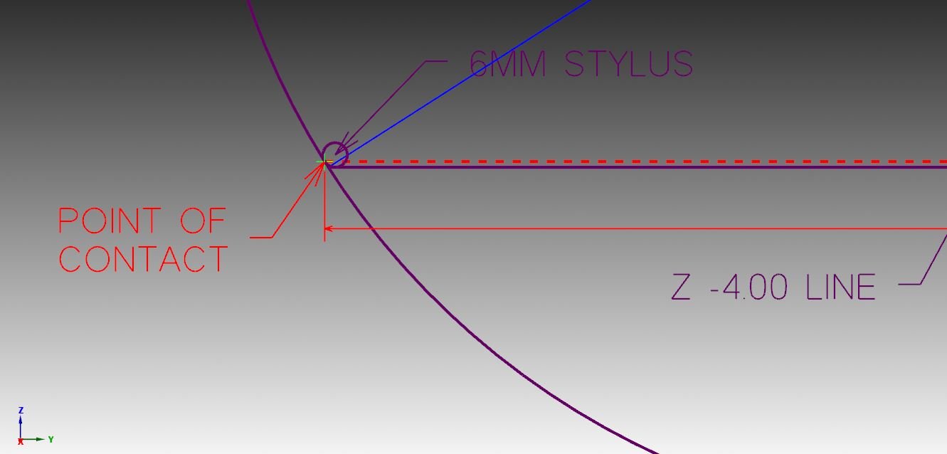
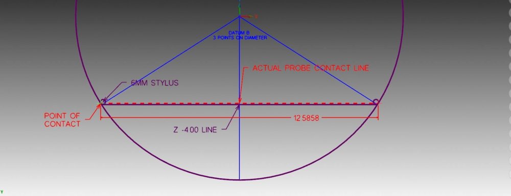
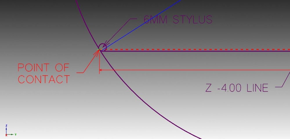
A few things I had to factor in The linier distance in Y must be a perfect representation for this to calculate the correct error. I did that by calculating the Y value of where the probe stylus actually contacts the diameter see illustrations. As you can hopefully see the radius of the 6mm ball actually contacts the part a little higher than the actual z-4 value called by the program, so I found the contact point and was able to come up with and actual linear value based on that contact line. Summery: All though this is functional, it is not a solution for this situation, problem is with out starting from a theoretical perfect z zero position, the linier value of the contact line will change, which upsets the error value. If it is higher then expected the linier would be longer, if lower it would be shorter, that could potentially lead to a work offset that is not where expected in the z. In the end I am just going to have to manually check the radius of each part on the CMM and update the z value of my original program from part to part, it will always find the center of Y no mater where in the depth I probe it and if I have a known radius I have my z value. Thank for all the help guys, hopefully this helps someone else down the road.
-
Here is what I came up with! More details to follow % O7699 (PROBE PARKER 7967460) G00 G17 G20 G40 G80 G90 G91 G28 Z0. T299 M6 (CHANGE TO RESHAW PROBE) M69 (UNLOCK) M11 (UNLOCK) G00 G17 G90 G57 B0 C0. M68 (LOCK) M10 (LOCK) G43 H299 Z.0 F100. G65 P9832 (TURN ON PROBE) G65 P9810 Y0. F250. (PROTECTED MOVE IN Y) G65 P9810 X-.6875 F250. (PROTECTED MOVE IN X) G65 P9810 Z-4.0 F50. (PROTECTED MOVE IN Z) G65 P9812 Y12.5858 S4. (PROBE Y AND SET G57) #540=#143/2 (DIVIDES LINIER ERROR FROM Y MEASERMENT AND SAVES TO #540) G65 P9810 Z-7. F50. (PROTECTED MOVE IN Z) G65 P9811 Z-7.427 S4. (PROBE Z ) #541=#5283-#540 (SAVES ADJUSTED RADIUS MEASUREMENT TO #541) #5283=#541 (ADJUST Z TO ACCOUNT FOR RADIUS ERROR) G65 P9810 Z0. F50. (PROTECTED MOVE IN Z) G65 P9833 (SWITCH PROBE OFF) G91 G28 Z0. (REF RETURN) G91 G28 X0. G91 G28 Y0 M30 %
-
So I talked to the Guys at Renshaw. Looks like to do what I want would require a strain gauge probe and newer software than what this control has. This is Just a OMP60 from 2011. But he made a recommendation that I am going to give a go. Since I am already probing the Y with a P9812 (web probe cycle he recommended writing the error which is recorded to #143 to a #500 then using that error to update my z value after running my P9811 ( z probe cycle). And that might get me close enough. I am going to play with this more Monday. I am letting you guys know all this because I have always gotten frustrated when searching the achieves for info, and the post went dead when someone figured something out. I am all about sharing, so once I get code that works I will post it for the world. Lol
-
When you are right you are right, I remember making a commitment to myself years ago, If I couldn't figure something out in 30 min I would ask for help. Here I go breaking my own rules.. lol Thanks Colin. This is outstanding and exactly the kind of stuff I love finding on the interweb, Thank you for sharing it. Weather or not I use it now it is definitely getting saved into my probing reference materials. Thank you
-
Honestly I did not know I could do a vector measurement in Z? Ill have to look into that a bit more. If that actually works its a done deal. But in order to do it in X I need to rotate to B90. and then use a disk style probe to clear the lip. The circle is cast and there for very choppy. I would rather use the same Datum target points the print calls out because Inspection will be using those as well. That datum is "as cast" to target points... so it never gets cut.... Real PITA! Then even if I could pull it off I have never really tried probing anything rotated, would no doubt require a G68.2 and some macros to record values and update X to Z and things like that. But I could be wrong. Definitely been hitting the boards hard seeking information about probing under rotation. Not coming up with a lot of information. I'm probably over thinking the whole thing and will end up setting multiple work offsets , but I hate doing it. Makes the operators job 3 times as hard for something that really is a few cuts... I like to help make my guys job ez so they can be successful, Hard enough to find good guys anymore, hate to scare the ones I have off. LOL
-
Also I think I'm getting closer to a math solution to define the radius. Basically I can get the linier width (record it) and I can probe the z from there that length = the saggita, with those 2 numbers I can calculate the radius excel formula looks like this =(B2/2)+(B1^2/(8*B2)) B2 Represents the box B2, which has the height (sag) B1 represents the boxB1, that has the linier width with that radius I might be able to write all the macros I need to set the z on the machine?
-
I do like that idea , Might have to run that up the chain of command. I can tell you that we have grown accustom to waiting around weeks at a time for an inspection, So I don't see how that could complicate things any worse.. lol that was a joke, but definitely a viable solution. Knowing the radius on each part would make my original probing routine completely full proof, just adjust the Z number in this line of the code G65 P9811 Z-7.427 S4. (PROBE Z )
-
here is a more accurate representation of what I am dealing with, the opposite end of the part also has a over hang, so really getting the 3rd point in the z is the only option I can see
-
Great suggestion, bad situation for it. The model I made is far from a true representation or the part. I has a .750 lip around that feature from the side. Otherwise I would have just rotated it 90 and probed it with a 3 point vector circle. to do it on this part would require changing the probe tip to a big disk, And the machine has 5 other pallets running various parts that require a standard 6mm probe ball. That and at this point I'm infatuated with how to do the math.. lol
-
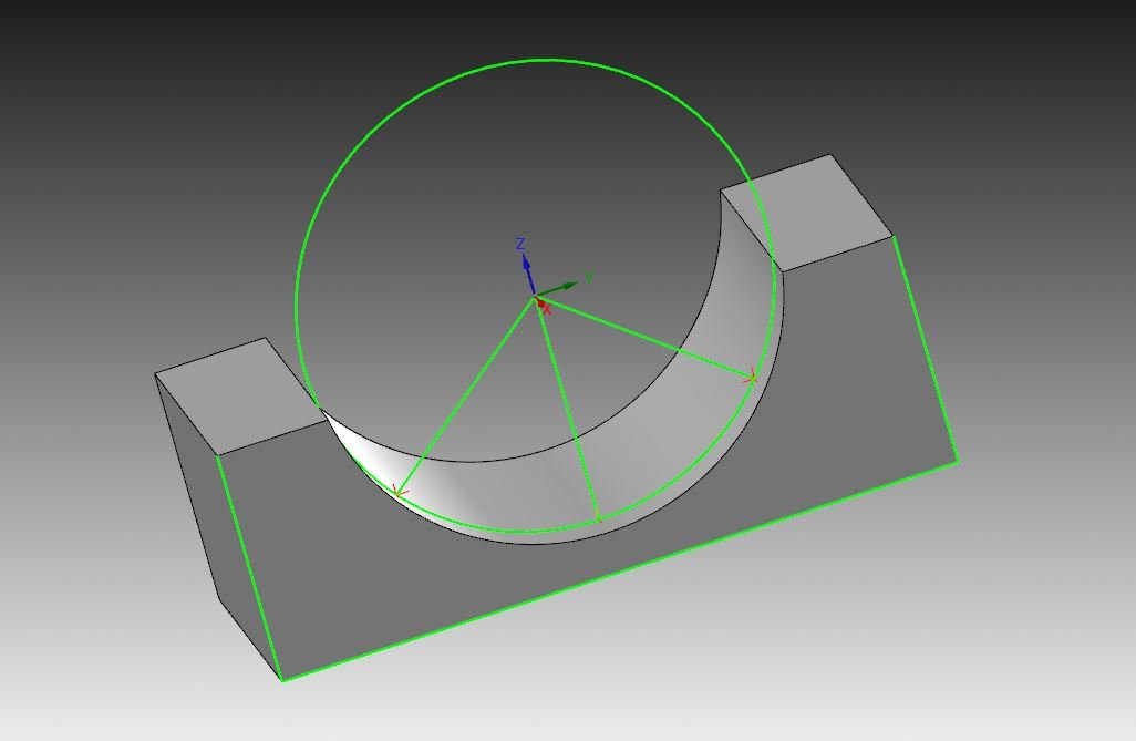
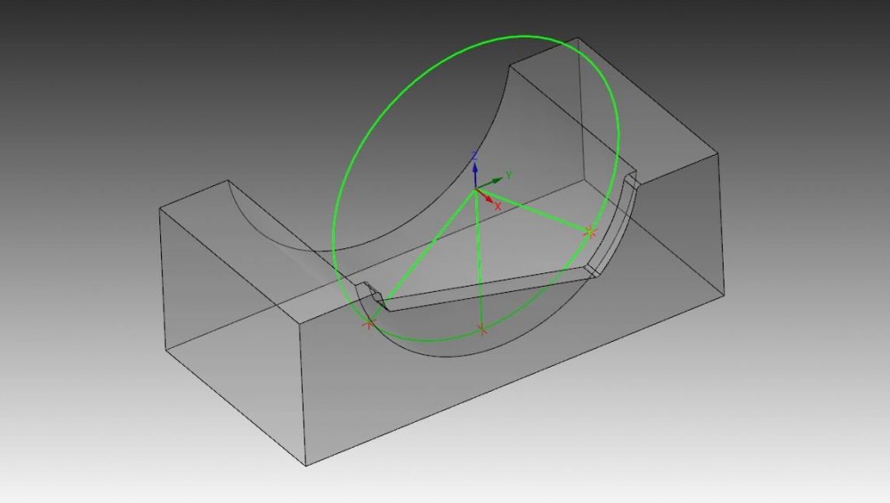
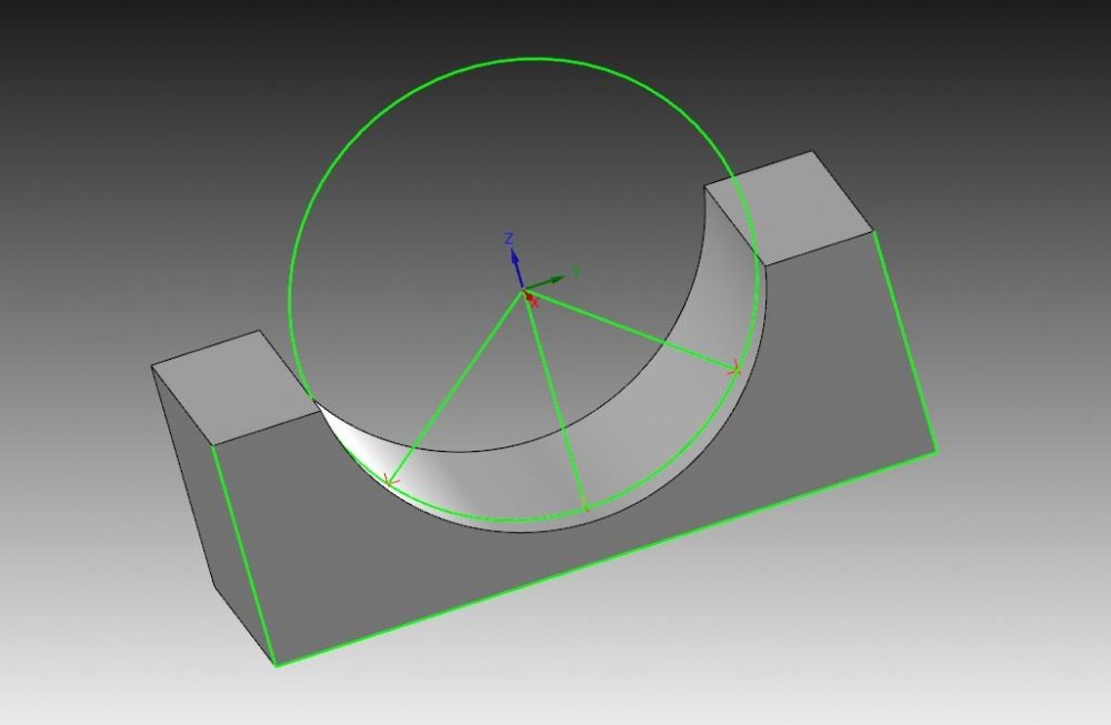
So this one is for brains bigger than mine. I have a casting and the datum target points are the center of a diameter. This diameter lies perpendicular to my Z. Ultimately it is not hard for me to probe to find the center of diameter in Y and then probe the Z to adjust my Work offset. See program below O7699 G00 G17 G20 G40 G80 G90 G91 G28 Z0. T299 M6 (CHANGE TO RESHAW PROBE) M69 (UNLOCK) M11 (UNLOCK) G00 G17 G90 G57 B0 C0. M68 (LOCK) M10 (LOCK) G43 H299 Z2.0 F100. G65 P9832 (TURN ON PROBE) G65 P9810 Y0. F250. (PROTECTED MOVE IN Y) G65 P9810 X-.6875 F250. (PROTECTED MOVE IN X) G65 P9810 Z0. F100. (PROTECTED MOVE IN Z) G65 P9810 Z-4.674 F50. (PROTECTED MOVE IN Z) G65 P9812 Y11.6 S4. (PROBE Y AND SET G57) G65 P9810 Z-7. F50. (PROTECTED MOVE IN Z) G65 P9811 Z-7.427 S4. (PROBE Z ) G65 P9810 Z0. F50. (PROTECTED MOVE IN Z) G65 P9833 (SWITCH PROBE OFF) G91 G28 Z0. (REF RETURN) G91 G28 X0. G91 G28 Y0 M30 The problem is the castings are all over the place in the diameter, So I need a way to calculate the true diameter from the 3 points so the Z can be adjusted properly. Hopefully that's clear enough to understand what I'm asking. I know I can store values and do calculations by adding some macros, but I'm not sure what the equation should look like. Any help is appreciated, sample file attached so u can see what I'm doing. Thanks in advance CASTING PROBING EXAMPLE.mcam also a screen shot for those that dont wanna download the sample file
-
Thank you for the share. I will plat with it and see how it makes since for my purposes.
-
I take it u didnt click the link. lol its more a PDF of a spreadsheet that exists somewhere..