CamMan1
-
Posts
283 -
Joined
-
Last visited
CamMan1's Achievements
")


-
 CamMan1 changed their profile photo
 -
Sorry I didn't back till now to thank you all. I kinda got behind resolving the gouge issue. It had bit me in the past and I decided I wasn't going to let it happen again. I have been told to just move on and figure another way to cut it on the next one. Well I was bound and determined to do it the way I believed it should be done. I am kinda stubborn that way. I knew if I didn't take the initiative to figure it out on my own that no one else where I work was going to help. Just to let you know that after I modified the post I initially had my Ange Increment set to .1 and my Max Step set to .005. Wow you want to talk about a lot of code for a little pocket. IT was kinda comical. The control had such a hard time processing the code that instead of it looking like it was cutting 15 IPM it looked like .1 IPM. The operator swore that the tool wasn't moving. That's when I changed to .5 Angle Increment and .010 Max Step. Thank You All For Your Help. It was greatly appreciated and informative.
-
By the way it was the post Guru over at MLC Cad in Dallas that pointed me in the right direction. Thanks Jeff.
-
Thanks much for the effort Cjep. I will take this into consideration. Thanks Much.
-
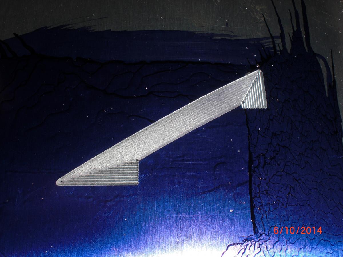
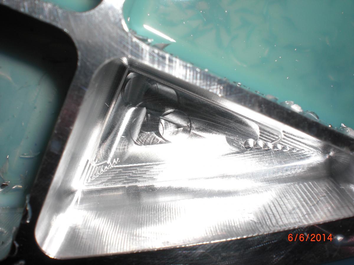
Yes it is a 16M control. It was built November of 1995. I hate to admit it but I have no idea what an NIT system is or APT source. Could you please explain. I really appreciate the feedback. We did manage to eliminate the problem. We changed the post by adjusting brk_mv_head from 3 Degrees to 1 Degrees and changing brk_tol from .001 to .0001. Then in my parameters in Swarf I changed Angle increment to .5 Degrees which I did not even have turned on. My Bad. Then changed Wall Following method to Cut Tolerance of .0002 and Max Step to .010. I attached pictures to show the difference it made. Went from .010 deep gouges to .0002 deep transition marks. I am happy with it as long as it stays this way.
-
Crazy Millman, Are you saying that you can use morph between 2 curves to machine the excess material from that undercut from the top down to the floor? I did use Morph between 2 curves to lollipop the curved surfaces on the inside walls. I didn't think there was any other way to remove the undercut material except for one of the swarf toolpaths. I know I can create multiple WCS and use some Legacy paths to get the job done but that is not what I want. If you have the time I would greatly appreciate the help if you could shoot me over an example. I am definitely open to learning new tricks. Thank You Very Much for your input.
-
I would really like to stay with this type of toolpath because for me it is faster than what our other programmers are doing. And I am the one who does the majority of the 5 axis programming. Do you think I should just machine it a totally different way or will the new swarf possibly fix my issues?
-
Yes Aaron you are correct with the no TCP. And from what I am seeing on the machine it is what you are saying. The tool is making an angle change before compensating for the tip which is sweeping the ball into the floor.
-
Thanks for all the help. I will take your suggestions into consideration. First rule of order will be some adjustments to the post. It looks like it is removing some of the moves that are in the corner which is being removed by a max angle setting. Looks like we will be doing some trial and error on the post and the geometry till we get this straightened out. This type of cut is commonplace at our shop. The other programmers are afraid to try this type of cut so they will create multiple WCS and they will flowline or parallel cut out the excess and then use projected cuts for cleanup. It is too time consuming for me to do this but if I have to I will.
-
The gouges are on the floor only. The further from the wall the deeper. The walls look great. When the tool is transitioning in the corner to change direction I am getting a pretty big angle move on the machine. Not nice small moves like I am seeing in backplot. It looks like the tool is changing angle before lifting the tool to compensate for the ball diameter. It looks like the tool diameter is stationary in xy when it changes angle which rolls the diameter into the floor before the tool lifts.
-
I was hoping Vericut wasn't that big of a deal to setup. I have been Trying to get a G-Code simulator here where I work but they don't want to cough up the dough. I was trying to explain to them that if we are going to do 5 axis work we need to have it. The other swarf cuts along the inside profile of the part cut just fine by the way. The machine has just been worked on by a reputable company to adjust the accuracy of the machine. All the toolpaths verified just fine in UVBS and the Machine Simulator. Anyhow attached is the partial file. SNKPC60V 5 AXIS GOUGE ISSUE 2.MCX-7
-
Could someone who has Vericut with a Head Head machine run some code thru and check for gouges. I have a small swarfing pocket in a part that is gouging the floor on the machine but it doesn't show up in Backplot or Verify. I can provide a small sample X7 file for it if necessary. I can't release the whole part file because of the nature of the work. I have never used Vericut so I don't know what is needed. We are trying to eliminate if it is the machine at fault. The machine is an SNK PC60V Head Head with 25 degrees range. Any help would be greatly appreciated.
-
Check this thread. http://www.emastercam.com/board/index.php?showtopic=77370&st=0 Richard and I have been looking at this. No word back yet
-
Thanks for the quick response.
-
Could someone please give me an idea what feeds and speeds and step overs to use with 2D Dynamic Core mill. We are cutting some 410 stainless at 43 RC. We need to cut 1.530 deep using 3/4" 5 flute Hanita Varimills with 1.625 length of cut. We are removing approximately .750 from profile of finished part. Any help would be appreciated. Haven't been able to find any data on cutting 410 this hard. I'm helping out our other programmer. 2D DYNAMIC CORE MILL.MCX-7
-
Only works for lathe and mill-turn right now.