BNFab
-
Posts
46 -
Joined
-
Last visited
Content Type
Profiles
Forums
Downloads
Store
eMastercam Wiki
Blogs
Gallery
Events
Everything posted by BNFab
-
Lets see the machine, its an e-1600V?? I used to run a few 1550's , bitchin machine!
-
From what I last heard the prices are really low right now. That is probly the issue.. I have heard of 10-12$ a pound, I think pricing is just in the dump currently.
-
Holy smokes that is AWESOME!
-
As others have said.. Mitsubishi is great, what I have always used.
-
I've used the MItee Bite expansion clamps on quite a few different parts. They work well when they are needed.. Generally ive used more than one at a time though, not a single one. Used them on horizontal parts, 5 axis mill turn machines (40" mill - turned parts) etc..
-
Disregard this post
-
Ok I dug a bit more, and I found a "Null tool change logic" segment under ' papproach0 ' If I insert my tool length setting on , and all that it seems to post correctly... Hopefully this works and only affects this area..
-
I dont know what section that is? Can I do something like this? pfzout #Force Z axis output *sgtlng_on, *tlngno$ if absinc$ = 0, *zabs, !zinc else, *zinc, !zabs , ms_z = zabs I added the first line , *sgtlng_on, *tlngno$ it seems to work.. Except for the initial call, it double posts the g43, .
-
So more post trouble... the post wants to output a safe index (g91 g28 z0) between paths... Ok I am fine with that at this point, but it doesnt recall the tool offset... How can I add this between index's so after the offset is called for the next rotation it will post my tool length comp? Thanks
-
Yes I have a .psb with it as well Does this mean I cannot edit the .pst?
-
It is a post I had finally got from InHouse.. Not sure what post they build off of. I literally am 2 months deep into this, and I would prefer to try and just make a small alteration if I can myself instead of trying to go back through the dealer/inhouse... I had received the inital post over a month ago which did not even close to match my sample code, sent it back and it took another month. I just cannot wait this long I really need to get it sorted out... Makes my life stressful
-
No I dont. I want M1's between tools for OP Stop. But not inbetween toolpaths within the same tool. Like every B rotation, it is posting an M1. I am not seeing a prog_stop switch at the top of my post Colin... I will keep looking for something that makes sense though, and see if I can make it work
-
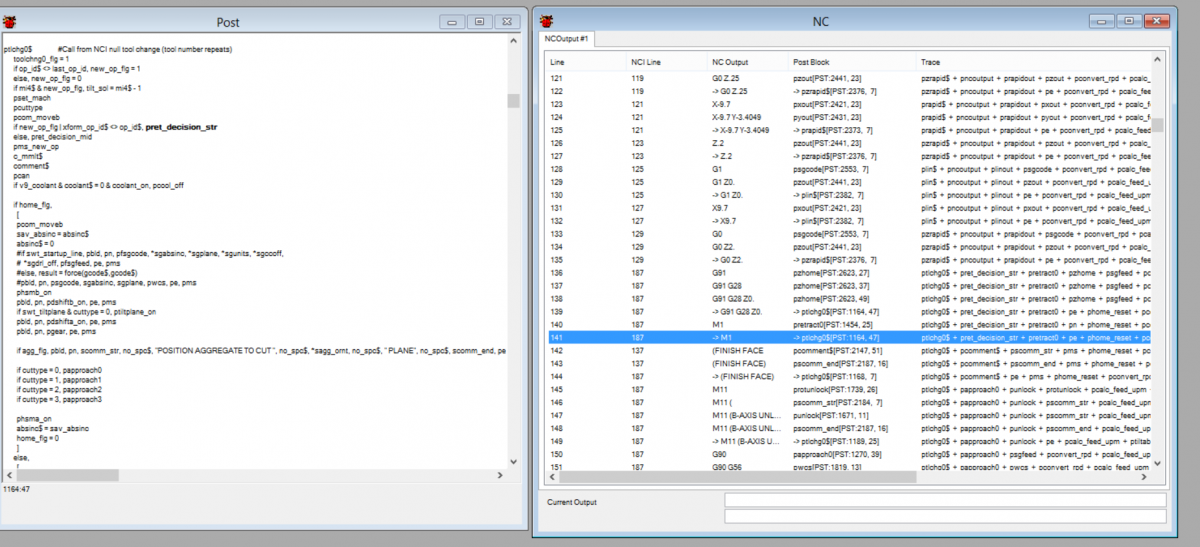
My horizontal post I am working on seems to be posting an M1 between paths. For example, I am facing 4 sides, and this is what it posts: ...more code up here.... X9.7G0 Z2.G91 G28 Z0.M1(FINISH FACE)M11 (B-AXIS UNLOCK)G90 G56 X-9.7 Y-1.6571 B-90.M10 (B-AXIS LOCK)Z2.Z.2 I dont mind the safe retract, but I would like to get rid of the M1 in between paths. It doesnt have force tool change active or anything like that.. I have the debugger open, I tried getting rid of one of the associated lines I thought was calling the M1, but it also deleted the g91 g28 z0, which I prefer to have just for a safe index.. How can I get rid of this M1? I put a screen shot of my debugger at the M1 line. Thanks
-
Does anyone have a post I can try and use? I have been trying to get a post for at leats 6 weeks now and I still have not received a functioning one... Makino horizontal, Pro 5 control..... Thanks
-
He's still around , I don't know if he posts much on the forums though anymore.
-
Yes Capto rules.... Thats a 10.5" dia disc mill...
-
So I changed to a 3/8 lolli from the ball mill.. Verify and backplot looks WAY better. Looks like a normal pretty flowline. If I verify against the model, it just shows a few skim marks on the top surface (like where the radius would blend off) it didnt look that good with a ball mill. I just haven't done something like this before so I was a little weary, especially when I am getting to the end of my part, decent chunk of materaial (20x18x6) I dont want to do something bone head.. Haha Thanks all Sorry I can't share the model, this industry is pretty proprietary.
-
This is about as good a path I cold generate.. It has a few whack moves I cannot get rid of.. What do you guys think? Thanks surface finish flowline

-
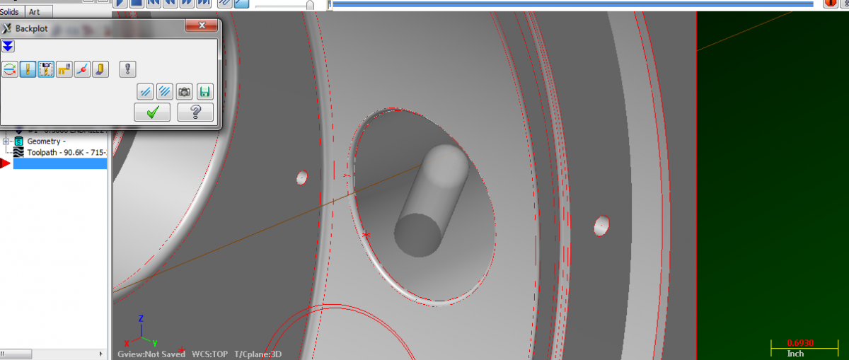
I am looking to try and machine this .100" Radius on the bore pictured. As you can see, it breaks through a into a large bore, so I cannot use an inverted corner rounder.. I was thinking of rotating the B (horizontal machine) about 50 degrees and trying to attack it from that angle.. I should be able to clear the machine spindle, or I will need to use a 12" long tool or so. Not a huge deal I think it will be ok with maybe a 1/2" ball mill... Just looking on some opinions of these, if it is feasible. I attatched a small photo of the feature and tool plane

-
I really just want to move the unlock/lock. I want it to unlock before it calls a workoffset. Then position the B axis on the line it calls the offset, then lock after that line
-
Ok, I will have a look there. I am new with editing posts, never looked at one before.. The sequence number works, but it doesnt save it in the control definition? Any reason why?
-
I got it to post this : N108 M11N110 B0N112 M10N114 G0 G90 G55 X-10.2999 Y9.4001 S9500 M3 I want it to post: M11 G0 G90 G55 X-10.2999 Y9.4001 B0. S9500 M3 M10
-
Looking for some insight on editing the generic Fanuc 4x horizontal post... I need to have it do a few things: 1. Post B axis unclamp/clamp codes (M11,M10) 2. I need to force it to post H1, D1 for all the tool offsets/cutter comp values. 3. Post an N number only at the start of each tool (based on it number, T20 would have an N20) That is about it for now, at least enough to get me going ok. Thanks for any help.
-
I cannot seem to make this work?? In previous versions I had no problems. Now I need to lead in and lead out from a point along a simple circular chain. All I can get it do now is to drop in at the point, then it tries to feed across (through my part) to where it wants to start. I turned off the start at midpoint button..
-
Hey thanks for the help guys. Maybe tomorrow I will post it here to try and figure out how to fix that one side. I was able to get 3 of the 4 to work by just creating wire geometry from the solid (curves) and using the swept surface function I was able to create the surfaces I needed. I still couldn't figure out how to chain the spline as one entity. One of the curves was broken up into like 8 line segments, the others were one solid spline. I just cheated and mirrored the one surface to the other side. It toolpathed just fine