Maclaw
-
Posts
56 -
Joined
-
Last visited
Content Type
Profiles
Forums
Downloads
Store
eMastercam Wiki
Blogs
Gallery
Events
Everything posted by Maclaw
-
Opti-rough with ballnose endmill causes collisions
Maclaw replied to Maclaw's topic in Industrial Forum
I tested the thing and have one conclusion when using a ballnose endmill in opti-rough: Use it with deep cuts and shallow stepovers - you should be safe - at leas from what I've tested a few times. If you try to use it with shallow DOC and big stepovers, you might get trouble with it colliding. Maybe not always - but be ready for it What I tried to do before was using opti-rough with a ballnose with shallow DOC and big sidestep (I had a 25mm ballnose insert cutter - not solid endmill) - similar to a "constant-z" like approach but with opti's great stock awareness and the possibility to add additional stepovers if needed to take out excessive "lands" of material. I considered that it shouldn't be a problem, but it seems I was wrong. This approach works out great though with bullnose endmills and what's more important - with insert cutters whose nature of milling is shallow DOC and big stepover. I use opti very often to take out material with insert cutters/high feed cutters etc. The approach is to go down in Z by the "millimeter" (+-) and take huge, but consistent sidesteps. No up-step usage because DOC is small. But with solid tools the thing is opposite - big DOC and small sidestep + upsteps - to fine rough out of the angles on surfaces. Anyway - beware with ballnose with this approach. I hope this helps. Take care and all the best! -Maciek. -
Crazy^Millman, Colin - big thanks for all your suggestions. Sorry for the long time with the response - I was stuck in urgent and precise prototyping work last week... Since nowadays I'm the only programmer/technology guy in my shop - I was busted 100% I did try what You told me and unfortunately it did not bring any effect I turned off "minimize trimming, then "Fit Transitions" and then both of them - nothing changed. I also played with the length/arc radiuses etc. in the leads with no success. I had to give up because the workload is unforgiving.. I will send it to my reseller and let Them deal with it. But first I have to prep the file since the original is under NDA... I hope the fake one will be curtious enough to reproduce the bug if I get feedback I'll post an update. Take care! -Maciek.
-
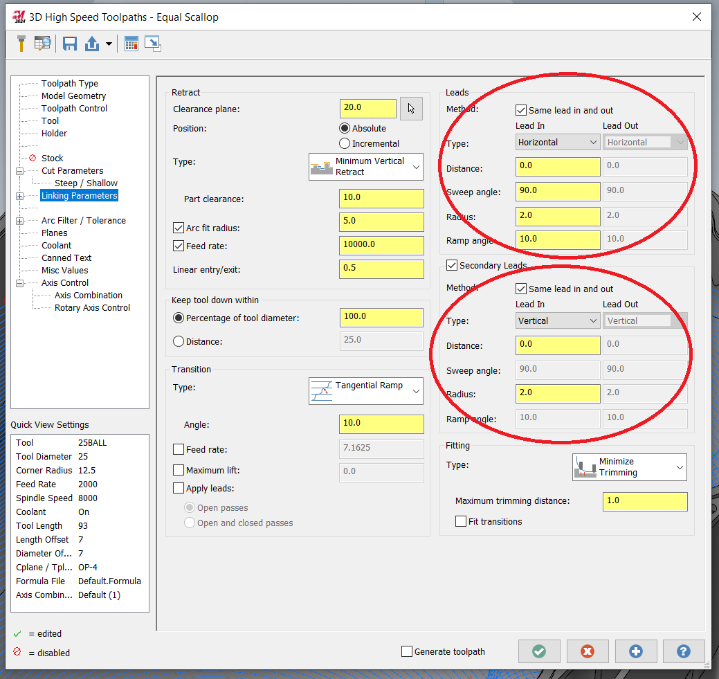
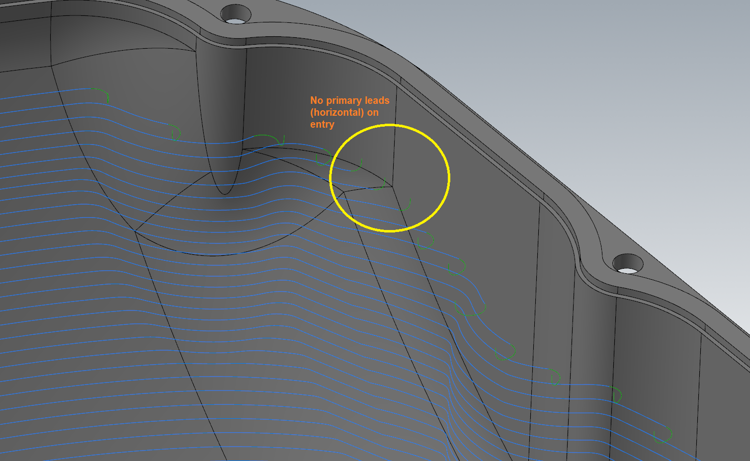
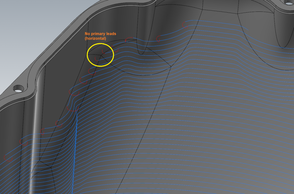
Hi All! Does anyone have this issue in equal scallop that it sometimes and randomly misses lead in and/or lead out passes? To be more specific - not the whole leads, but just portions of it, ex. primary lead or secondary lead... I attach pictures to explain what I mean. Maybe it's me doing something wrong - I don't know... Anyway - this is annoying, because it doesnt feel you have full control over the thing... If anyone has a clue what's wrong - I'll be grateful. I can't attach the MCAM file because of NDA... I tried to explain it on pics only... Sorry and thanks!


-
Tried to make a dummy flowline to see what your having. I noticed that if I toggle, let's say the "Cut direction" button, after 3-4 toggles all the plots dissapear, even the cut direction arrows, which in your case stays on the screen. If I then rotate the graphics view or just "touch it" with the middle mouse button, the plots and arrows appear again. Maybe this will help you... Anyway it's just a workaround, but it may let you at least proceed forward.. There is also the "Plot edges button" but it seems do do nothing... Another thing - remember to click the button with the flow picture (on the bottom of the window in the "Flowline" section) in the "Toolpath/surface selection window, taht appear just after you select your surfaces. Good luck!
-
You have to have projection set to 3D instead of 2D on the Cut parameters page. Then You can use tool contact point with the curves (dont confuse it with the boundry). I dont know why this is so, but that's the way it works. I struggled with it for a while also... But You propably know this by now - I'm a year late sorry
-
Please Explain the difference between VC and SFM if any?
Maclaw replied to [email protected]'s topic in Educational Forum
Both Vc and SFM are a measure of linear peripheral speed of a tool in reference to the material it cuts. Both are proportional to the RPM which is the angular speed. So RPM causes Vc (and SFM) and the latter is the speed at which the tool cuts (rips off) a layer of material. This cut layer has a mean thikness equal to the mean thickness of the chip (hm) and depends on fz - feed per tooth. Vc is in metric units while SFM is in Imperial units. Vc is the cutting speed in meters/min, SFM is the cutting speed in feet/min. Common formulas in a nutshell: Vc = Dc * PI * RPM / 1000 where Vc is in [meters/min] ; Dc is in [mm] ; RPM is in [1/min] ; Dc is the cutter diameter SFM = Dc * PI * RPM / 12 where SFM is in [feet/min] ; Dc is in [inches] ; RPM is in [1/min] ; Dc is the cutter diameter To switch between them use these formulas : { Vc = 0,305 * SFM } or { SFM = 3,28 * Vc } Hope this helps. Take care! -
Opti-rough with ballnose endmill causes collisions
Maclaw replied to Maclaw's topic in Industrial Forum
I went with 45% sideways because of a small stepdown. Did not want to waste that much time. A ball can handle 45% sideways while 6% deep in aluminium no problem. I would also need to trim the path with some "dummy" stockmodel to make it stay off the sphere that was previously roughed with the big tool, but that's a different thing. I know you didn't mean ill will. Me neither. I try to focus on the problem and then tackle it. I rely on Mastercam everyday, even though I do not consider myself a power user. But if something goes wrong, I do worry and - if time provides - try to dig upon the subject more deeply to solve it and explain what was the issue. Since time is my enemy - a lot of times I just go around the problem and at the end of the day come out the same door only from a different corridor... And that I love in MC because it gives you the freedom to do so. I will try to test this "ballnose opti thing" deeper and will let you know what my conclusions are if they will be worth it. Hopefully, in the meantime will also read what others say. Thanks and take care!! -
Opti-rough with ballnose endmill causes collisions
Maclaw replied to Maclaw's topic in Industrial Forum
Crazy^millman, wow! Thanks for your help and good advice but unfortunately it did not go in the right isle... I think you misunderstood my question and my problem. That's propably my fault - English is not my native language But to be honest - I don't really understand why you are talking about metetrs of flat areas milled with a ballnose leaving cusps etc. Have You seen the part I attached? If not, be informed that the part is a sphere with 4 vertical technological bosses attached to it which are filleted to the sphere with R10 mm (394 thou radius). From my 15+ year experience, a ball cutter was the first choice to clean up the fillet radii from material left by the 25mm bullnose that I roughed the thing out with... "Beat me up Scotty" - but unfortunately that was my first choice! Sorry it wasn't the face mill nor the flat or bullnose... I admit - the microlift was my overlook which gcode fixed quickly - thanks again gcode Remember when I said "...if You play around with the step-over/step-down/step-up in the file in the toolpath that uses the ball - you could get even worse collision scenarios..."? Well here is one : The same toolpath that gcode fixed - the change is stepover to 45% (3.6mm), stepdown to 6% (0.48mm), step-up not used, because stepdown is small enough (I wanted to use a constant-z like approach with additional side steps if needed). And guess what - you get collisions! This time the microlift is 1mm and the maximum cusp height that is derived from the stepover is: c = R - sqrt[ R^2 - (s^2 / 4) ] = 0,428mm (the microlift in the path = 1.0mm - so it should be safe) where: c = max cusp height (provided you mill off a layer >= the cusp height) R = radius of ballmill (4 mm - it's a 8mm ball) s = stepover (3.6mm) So why are there collisions? Can you explain? Bad craftsmanship? Bad program to do the job? Bad toolpath/tool usage? Bad day? Bad week? Bad what? Well - I don't know the answer - that's why I asked people that are smarter than me - maybe they will come up with something, maybe they had issues like that in the past... I think that this question is also adequate to people who created the software - they know best their intension with this toolpath. If they say - try avoiding or take special care to this opti toolpath with ball endmills - that's fair enough - that's some info at least. But in the end - I think this should be fixed - it might be in 2025, 2028 whatever, but something is said about it and some secrets revealed and some foundation built for the future of this magnificent - after all - software! Step by step - that's how it looks in my world... I attached a file - it's operation no. 5 that generates these collisions. Operation #6 is for comparison, that a bullnose does not have these problems. It has the exact same parameters - only the tool is changed. Crazy^millman I really respect all your knowledge, experience and professional expertise - really. You rule on this forum! But I don't like misunderstandings, hence all the above. Also don't worry about me getting "all butt hurt" - I don't have time for such soap opera BS - I'm here to get rid of a problem - pure and simple. Anyway, my last thought is that this problem DOES need answers and a remedy. All the best to You all! OPTI WITH BALLNOSE.mcam -
Opti-rough with ballnose endmill causes collisions
Maclaw replied to Maclaw's topic in Industrial Forum
Thanks gcode. Tried it and it doesn't collide. You could say case closed, but... Anyway - from my perspective - that's a workaround. From my point of view - the toolpath shouldn't do that. Opti is a very powerful and almost automatic roughing startegy in conjuction with stock model. But the most important thing for a programmer is it's reliability. You must be able to trust it! I know, I know - you should always verify and simulate it, but if you get a problem - it could take you more to make it work than sometimes roughing the part "manually" using other paths. So my theory is to rather use bull-nose due to the flat portion that it has - it doesn't generate scallop. Seems opti isn't so comfortable with this scallop generated by a ballnose and may collide. I did this in aluminium - that is a very forgiving material. If you were to mill an exotic... - it definetely would be a problem. I also have a question to the Developers of MC : Is Opti-rough more dedicated to bullnose than ballnose? Does the above "theory" make sense. If yes - than I will do that - will avoid ballnose and the case is closed for now - hopefully it will be more bug-free in the future. What do You think? Besides if You play around with the step-over/step-down/step-up in the file in the toolpath that uses the ball - you could get even worse collision scenarios. Can the Developers make their opinion on that - that would be very useful and life-saving info for all of us. Thanks very much and looking forward to your opinions. -
Hi All, Has anyone encounter problems with ballnose endmills in optirough (rest) toolpaths. What I've recently noticed is that this toolpath, when used with a ballnose endmill, may occasionally cause collisions with in-progress stock. This can be seen in verify - red color or in the report tab. The collisions regard the flute (cutting) portion of the tool. I attach an MC file with a dummy project to look at this. The EXACT same toolpath (copied) is used with a bullnose and the collisions disappear. If anyone has any thoughts about this - please let me know. The file is metric. Thanks in advance! Maclaw. OPTI WITH BALLNOSE.mcam
-
Just made the Benchmark 3.0 test on 2021 (fresh open of file with 2021, clear log, regen all ops in the tree, no edits, no save, nothing) : i7-3930K @ 3,2GHz, 32 GB DDR3 RAM, NVidia GeForce GTX 1660 PLUS, 480GB SSD, Win 10 Pro x64 - all self-built in 2013 - only added the bigger SSD and new GPU - today 1) No of threads = 4 ; priority = NORMAL -> 5:46 [min:sec] 2) No of threads = 8 ; priority = NORMAL -> 5:26 3) No of threads = 16 ; priority = HIGH -> 5:19 4) No of threads = 6 ; priority = NORMAL -> 5:25 No big differences when messing with the thread # and priority. The result didn't knock me off the chair, unfortunately Well maybe it's time to look for a new machine... I still wonder wether the GeForce GPU is a good choice and does it have anything to do with the toolpath calculations? Anyone have a clue? I'm asking because the Quadro prices are at least twice as those of GeForce. And last (but definetely not least) - Quadro's parameters are usually worse than those of GeForce (amount of memory, amount of CUDA cores, memory bus width, memory clock rate, etc. - my logic tells me that these are after all very important parameters)...
-
Thanks Crazy^Millman I'll give it a shot Does anyone know of a benchmark regarding graphics for 2021 or other versions? How to test your system as it goes for the GPU to know you are good (or not)?
-
Where can I get the file - I would like to test it... Thanks in advance
-
Okuma Subroutine Call OSP-300
Maclaw replied to gcode's topic in Machining, Tools, Cutting & Probing
Thanks Mr. M, But unfortunately when I use scheduled progs the machine doesnt display the program flow... And this is an issue in my company. It's against our internal safety procedures - how can an operator run a program "in blind"??? This is some kind of absurd....!! Anyway - thanks very much for your interest in this subject Mr. M. I guess for now I will go with the ".ssb" method from the root of MD1, as Brad described above - already backed up all files from that directory in case I or someone else deletes anything important from there. Thanks again Brad for your post. It's amazing how this machine is "safe". You cant even use an edgefinder at 400 RPM with the doors open (max RPM=50).... But when you run a scheduled prog it wants you to do it "blind" - aint that clever Folks? BRAVO!!! :-) The Guy who came up with this clever idea should go to Swedem for a Noble "anti-common sense" prize! I mean - dont these darn MTBs listen to the machinists anymore these days??? Why?. Good thing I also have HAAS machines which are made for machinists and can be operated in a normal manner still maintaining RESONABLE safety issues. They say Haas this, Haas that, but.... oohh man... to move axes (while spindle is stopped) in this Okuma, it would be good to have 4 hands and a checklist procedure like airline pilots - so many buttons and key switches you must press to achieve this. Going this way, in a few years you wont be able to touch this machine while working on it... This is crazy!!! It's so darn sad they screwed these "little" things up so much - in - at the end of the day - a resonably fast and rigid machine which must say the okuma is. It's just sad. But when working on a daily basis these "little" things just make you go mad.... aaahhhhh!!! Anyway - sorry for the sorrow words but I just had to say it However I will still try the ".sub" method in free time (if it's possible at all). Anyway when I come up with something will let you all know. Take care Folks :-) -
Okuma Subroutine Call OSP-300
Maclaw replied to gcode's topic in Machining, Tools, Cutting & Probing
Hi Brad, I want to use the ".sub" method. Why cant I select MULTIPLE (not just one) subprogram file? Do You know a way of achieving this??? Because what's the use of having a main .min program calling just one subprogram .sub file? I prefer using the .sub method because I dont want to trash my root MD1 directory. I want to use my machine to do 4 pallets of different parts in one run. I will post out 4 part programs and want to have a 4 line main .min prog to control which subs to execute. I dont want to do megabytes of copy paste stuff to put it in one file because it's annoying, a lot of work and may also be dangerous if you leave something out.... Beside - this week I will do 4 parts at a time on 4 fixtures/pallets, next week I will do another (different) 4 parts. All I would need to do is post out the 4 progs for the new parts into subs and do minor (or none) editing to my main prog and fire of the production with no windows copy/paste BS and merging large files into one and all that headache.... Thanks in advace for your help. -
Hi Is1wot, No - I still havent figured it out... Liearizing arcs did not change much. Like SlaveCam wrote a few lines up in this post - I simply dont use SUPERNURBS when roughing (thanks SlaveCam for Your post) - just use it to finish. Be aware that when NOT in SUPERNURBS the speeds are very nice and dynamics is brilliant - the machine "flies" fast and doesn't jerk at all - however You get quite significant machining erros - especially watch your outside sharp corners (especially greater than or equal to 90 DEG) - they can be rounded off by even 1mm (R = 1mm)!!! If I come up with something I will liet You know. Right now I a am pounded with loads of orders and work and don't have the time to experiment... :-( But it all is in the back of my head and waits to be remedied :-)
-
Yeah, I guess You're right Mark. We'll see what happens - I am not done with Them yet Will let You know. Sorry , but what do You mean by PM? I'm a little off - it's almost 1am over here....
-
Hi Jeff, What do You mean that the crush ring was out 0.00002"? maybe 0.0002 or 0.002 ? Do you mean the same ring I was talking about - the brass thing the is tight fitted into the cover in the bootom portion of the spindle?
-
Dzien Dobry! Well - I did rapid into material with an ae=1.5mm only (wanted to chamfer an existing pocket - it was OP 2 - the pocket was already cut in OP 1). That's nothing - I did not touch any holder or spindle housing or anything that's solid. The tool stopped rapiding before the fixture surface and then went down 1.5 mm into the fixture surface with G1 f=2500 mm/min. After that it went into a side cut without flutes with G1 f=2500 mm/min or 100 IPM. To me - this propably was the most problematic. But if the tool survived all this abuse - why the hell did the spindle give up....???? And if that was too much for the spindle or axis - why didn't the machine stop due to too much overload? The stickout of the tool was 37mm being just over 3xD. The thing that happened to my spindle is that a brass ring that was glued in or tight-fitted into a steel cover got loose and went in contact with the spindle shaft. This caused it to heat up and make bad noises. These parts are non-rating parts in the lower portion of the spindle. They are part of the air-seal along with the labyrynth that is a rotaing part (tight fitted onto the spindle shaft). Anyway the Guy took this ring out and assembled the spindle without it (with OKUMA's permission of course) - just to test it. It was OK - the temperature was OK and the sound of the spindle was also OK. I was quite happy that I didn't have to pay $30k for a spindle replacement What pissed me of after that is when I received a price and time offer for this part to be replaced : 1200 EUROS and.... You all better sit cause you'll fall : 2 to 3 weeks delivery time!!!!!!!!! Now that's the part that I suppose can go into the Guiness Book of World Records - into the chapter titled : "We dont give a xxxx about any Customer once he bought our machine". I'm out of words... hard to comment.... Well anyway - I'll tell You all what the service People tell me: 1) The machine did not stop because if it did the overload level would be too low to allow for "normal" operation during more aggresive cutting. I ask Him : well if the spindle cant handle this then the overload maybe should be set to a lower level, preventing the machine from self-destructing. He said that the machine cant think by itself - the operator must do that. OK - he's right. I know that there is no cure for a Guy who rapids 100% and sweeps everything from the table and at the end must run away in order not to get hit by the whole thing falling apart. There is no prevention from a RAPID hard hit - even if the machine stops - it's already destructed - that's common sense and you dont need to be aqualified OKUMA serviceman to figure that out. But in my case - the machine did not rapid but was fed into material with a reasonable feedrate and did not stop by itself - and this IS NOT NORMAL TO ME - unless the thrust on the axes were not exceeded. In that case - the spindle should also be that tough to to handle such torque on it's cutting end - that is a result of this axis thrust. If not then something IS WRONG. At leaset that's what I think and am pretty sure I'm right. 2) I will propably loose my warranty for the spindle - I barely made 800 hrs out of it - so - there goes the 20000 hrs for which the spindle is rated for... Just because of this stupid mishap. Anyway - I still an fighting with them and dont want to give in. This is crazy - I'm still not believing it's OKUMA... That's like nothing I ever heard about this brand... Unbelievable. Sorry Everyone for such a long post - just wanted to tell You all I know. Thanks and take care. I wish You all not to have such happenings - or mishappenings :-) Take care. Do zobaczenia (See You later)!
-
Hi Everyone, I just had a mini crash on my GENOS M560R-V (the "european" version of M560V - no BIG PLUS spindle - regular BT-40). I went 20 mm to low in Z.... Was finishing the 2-nd OP on an aluminium 5083 (very soft) part. I had to chamfer a thru pocket and went in 20mm too deep in Z with a 12mm (~0.5") solid carbide chamfer-mill - 4 flute. The endmill survived the G0 Z plunge and went on cutting in -Y direction buried 20 mm in material. The side cut was about 0.4D since I wanted to chamfer a pocket. The problem is that it had no flutes on most of the height of the cut since it's a chamfer mill - has only flutes on the 45DEG part of the tool (6mm flute lenght: 12mm / 2). The cut lasted for about 70 mm in -Y distance when I finally hit the E-stop (this is a very different story that I am ashamed of talking about ) - in the same time the endmill gave up and broke of. During this "cut" - or maybe should I say - forming - my part was displaced causing one of the 0.2" dowel pins that held it in proper position to break off of the fixture. Today a Service Guy came in, checked runout, machine geom - all seems fine. But the spindle rotation is not good - the sound is not clean - not good. He worries that it might be a spindle replacement issue... I was like - WHAT??????? Okay - I hit the baby a little - but what.. - it means I killed it...? Did not hit with the toolholder , dit not hit with the spindle - just hit the tool. Anyway - tomorrow he will come back and we will disassemble the lower portion of the spindle because the sound it gives is not proper - that's why I called Him in the first place. I am a little dicouraged - tomorrow I will know more. Will also let You know. Anyway - what do You Guys think of this? Did anyone have similar crashes and afterward spindle issues? This machine was supposed to be a beast...! And I wounded it... with a 0.5" solid carbide tool in 5083 aluminium - this doesn't sound good... Maybe it was just completely bad luck and very unusual circumstances that all put together caused all this hassle... I dont know - will happily hear your thoughts. This or that - my advice is : be careful with your machines - ANY "crash" - even with small solid endmills can be dangerous - you dont need to hit with any steel parts or toolholders to make a mess. Take care of Your CNC babies out there. :-) I hope there is still hope for me... :-)
-
not to worry my Friend, not to worry just a few miles further to the east...
-
Yeah - thanks Jeff. Will try that. I'm based in Warsaw, Poland. The Okuma Distributer here is HTM in Gliwice. Will have a word with them regarding the subject. I will let You all know if I get any concise remedy regarding the subject. In the meantime I wish You all a Merry Christmas with lots of joy and great time spent among Your Families :-)
-
Thanks for your posts Guys. Colin, I used the old Surface finisz paralel toolpath. The toolpath at first didn't consist of any arc moves since I turned the arc filter off - so MC didn't generate G2 G3 moves. But... it did have quite long line moves in the toolpath - about 12-16mm. You're right - this might of caused the machine to go hi-speed on the long lines and then suddenly slow down on the linearized arc moves which were G1 moves of about 0.1 - 0.2mm - hence causing the jerking (you guys buy that explanation... :-) ). I will try breaking the NC code into small line moves and let You guys know how it worked. Besides - do you Guys think messing with the OTHER Supernurbs parameter which containes Accel/Decel etc. for all 3 modes (HQ, STNADARD and HIGH SPEED) might be the solution? The parameter I'm talking about is also called Supernurbs.... and in my machine it lies just after the parameter where you pick the tolerances etc. I have no acces to my machine now (am staying sick at home...) but will post a screenshot right after I get better and You'll see what I mean.
-
I tested these parameters: machine tolerance : 0.005mm to 1mm (!!!) program tolerance: 0.0025mm to 0.5mm (!!!) utilize reconst. shape : HIGH max block length: 20 min block length: 0.05mm to 0.3 mm (0.3 was the default). program filter : off and mode1 - the last did a little help. Filter length : 0.02mm filter angle : 0.5 deg used all 3 maching modes (HQ, STAND. and HI-SPEED). the last one jerked like hell - I thought I'd lose all my sheet metal... and stopped it after a few seconds. HQ was the slowest and jerked - but less then HS. I really did not achieve any satisfying results with playing around with these settings - not close to the ones on the youtube video. The strange thing is - when I turned Supernurbs off - the machine started flying with high speed and almost ZERO jerking - as it was placed on cuchion pillows :-).... I Wonder if the Guy that made the video did put supernurbs on at all...? Maybe it's just marketing BS... Sorry but just dont know. I put through 3 program types out of MC: 1) filter set to 0.02mm - no arc filtering - pure G1 lines 2) filter set to 0,0025 (like in the video) - no arc - pure G1 3) filter set to 0,0025 - with 50% arc filtering - the code consisted of a whole lot of arcs - almost no G1 curvature faceting. The code on this one was lik 3% of the one for 2). All three programs worked well without supernurbs (comparable with the video) and not even close to the video with supernurbs on. Ther is also another parameter (i dont remember what it's called - since am not by the machine at the momemt) for supernurbs that consists of varios accel/decel axis paramters. These differ for HQ STANDARD and HI-SPEED. I suspect that maybe that's where the detail lies...? But I cant find anything in the manuals (theres like a 100 of these manuals :-). Do you have something similar for Hi-Cut PRO - another machine parameter just after the one with the tolerances?
-
Hi Guys, Anybody had problems/issues while using supernurbs on Okuma Genos M560R-V? I just got my machine up and running and were doing some air-tests - wanted to see its dynamic motion etc. My first experiences turned out to be : it works better... WITHOUT Supernurbs! I just had to push the supernurbs upper feed limit parameter to 20000mm/min while still having : CONTROL OFF. When I truned Supernurbs ON - the machine started jerking it's brains out...! I messed with these machine/program tolerance, filter setting, block lenghts etc. - had no visible improvement. I programmed a part similar to the fancy X-Z movement zigzag that I saw on youtube (https://www.youtube.com/watch?v=p_vwe3kmDaE). I did it in MC X9 as a paralel surface along the X - feed was set to 10000mm/min and pumped it up to about 14000mm/min. I had a similar result as on the video - but with supernurbs OFF... Can Anyone explain this or also had issues with it? Thanks