Brian Pallas
-
Posts
183 -
Joined
-
Last visited
-
Days Won
1
Content Type
Profiles
Forums
Downloads
Store
eMastercam Wiki
Blogs
Gallery
Events
Everything posted by Brian Pallas
-
You can use Stock Model, pick your casting model as the start model, no operations selected, ands compare it to your finished model.
-
Back before I ever had with access to a Machine Simulation, I always made the spindle nose part of the toolholder. I’ve done jobs with the spindle inside the part with 5 axis cutting, or right up against a tombstone. No we have machine sim software, which is cool, but it seems the functionality of collision checking the spindle to the part and fixture within the toolpath is diminished, if you want it to work with machine simulation. Am I missing something? If the spindle is added to the toolholder inside the toolpath, the machine sim will not be accurate. There will be two spindles, essentially. So you would need to change the holder after making the toolpath, but that makes the toolpath dirty. In Camplete I think you can add a different holder to a tool other than the MasterCam tool definition, but a work around with holder models would be a source of error, if a change is made, it must now be made in two places. I feel like there has to be something I’m missing in this equation.
-
Thanks for the help and all the documentation James, I really appreciate it!
-
We fairly recently got Camplete with a machine purchase, and I was wondering if there are any good sources for learning to use it and the abilities it has other than just playing around with it? Either tutorials or videos I can watch at home, or perhaps a training source that the company could buy? So far I have been able to find some info on Autodesk's website to change some settings to get the code to change. Like today I noticed that I am not getting the R value output in my G05.1 line and found on the Autodesk website how to set that up, though I still need to actually make the change. I think we just bought Camplete from the machine tool company, and I don't know if we have any support options. Do the Camplete users out there just edit their own parameter's, or do y'all have a source for making the changes for you, similar to the MasterCam post editing? I like to learn, it's more of a time issue, so I'm curious about what everyone else is doing with that. I wish Camplete had a home learning module like Mastercam does. I've been getting code posted and am running it, but I know the software can do more than I know how to get it to do at the moment, and I feel like the workflow I have with it can definitely be improved. Thanks
-
In the settings, I think there is a minimum pitch field. I think mine is the default which is .0005. Maybe that?
-
I will make a toolpath with what I want, except top down. Then backplot and save the geometry. Then clean up as needed and make a new toolpath using that geometry. The other day I used circle mill for depth cuts on a back counterbore that I wanted to machine from the bottom up. I put a point at each depth I wanted and set all my linking parameters in "Incremental" and "0", except for the clearance. Is there a way to get depth cuts from the bottom up with one chain or point?
-
M73 and M74?
-
On larger npt's I've always used a ball to profile the minor dia with the correct taper, and then used an inserted single point threadmill. Like a sandvik 327(I think. It's been a while.) Or I think PH Horn makes one that looks the same. I usually take at least 2 rough passses and a finish pass with threadmill. For single point threadmills I always machine top to bottom.
-
I think I was wrong about starting with the mplmaster, because I don't think it woul've gotten encrypted. It was a few years ago, but I must of used the post the shop already had, and then I think I basically updated it all to mplmaster. So their post encrypted, which is weird, but ok. So yeah, I downloaded mplmaster again and just file compared and cut and pasted. Just about got it, wasn't that big of a deal. Just another setup step.
-
Morning, I have a post for a Mori NL lathes. It is just a MPLmaster post from this site that I modified to work how I wanted with the Mori machines. I used it at a different shop. Now I changed jobs, and I have a copy of that post, and I want to use it here. When I go to use the post I get the error "Post not encrypted to this sim". What do I need to do to get the post working here?
-
Swept 2d works perfect for this if you can get the first chain aligned with x or y. Then you create multiple tool paths if you need to rough and finish it.
-
I mathematically figure out the centerline position. Use that in X position on the drill cycle. So a drill cycle operation for each boring pass.
-
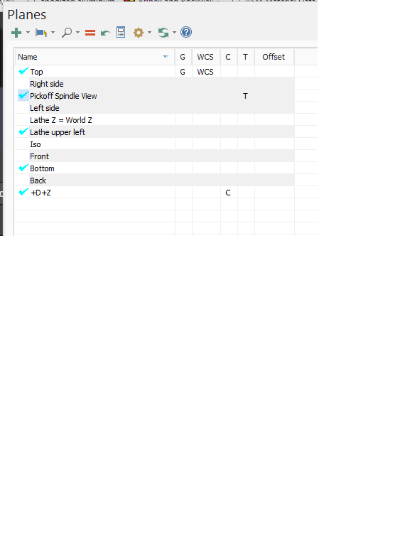
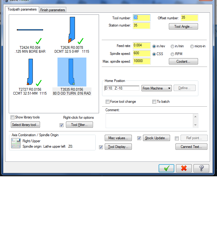
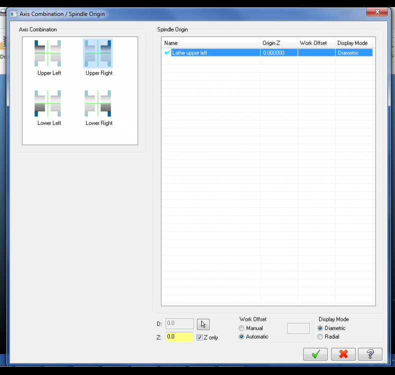
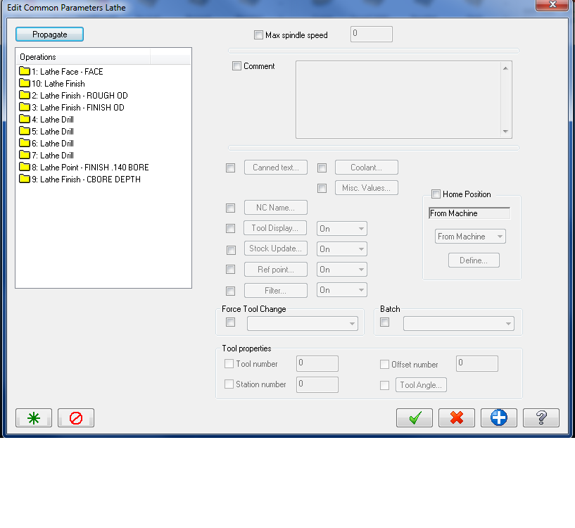
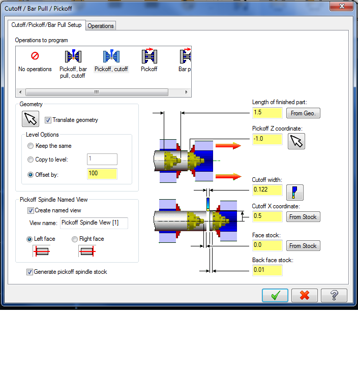
So in X7 when the stock would transfer from the main to the sub spindle, had it generate the pickoff view, then you would select that as your tool plane, do your toolpath and pick a tool for the sub spindle, and then Mastercam would automatically make another plane for the right side that had the same origin as the pickoff spindle view that was created with the POCO operation. I don't know what changed in 2017, or why it isn't working for me but now I select the planes as before, and mcam always wants to use the left spindle plane. It will say the axis combination is Right/Upper, but the "spindle origin" will still be "lathe upper left'. So I have to go in and manually make a new plane, then go to the toolpath, then reselect the planes in the "axis combination/spindle origin" area. Also noticed that for lathe you can no longer change the coordinate system for a group of operations by using the "edit common parameters"? Or did they just move that somewhere else and I'm not seeing it? Used to go "edit common parameters --> "coordinates" I've never really got why if I use the plane manager and select the plane, that it decides to use a different plane when I create the toolpath, instead of just using the pickoff view that it already generated? What is the right/easy way to get the planes made for the sub side?
-
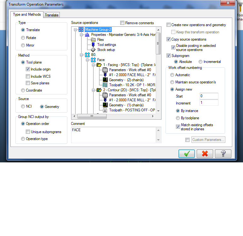
Aah, under the "Transform Operation Parameters" changing the "Source" from NCI to Geometry made it so: 1. The comment for the planes updates and 2. Made it so that if I change the plane work offset under the plane manager, that the posted output reflects the change without needing to regen the transform op.
-
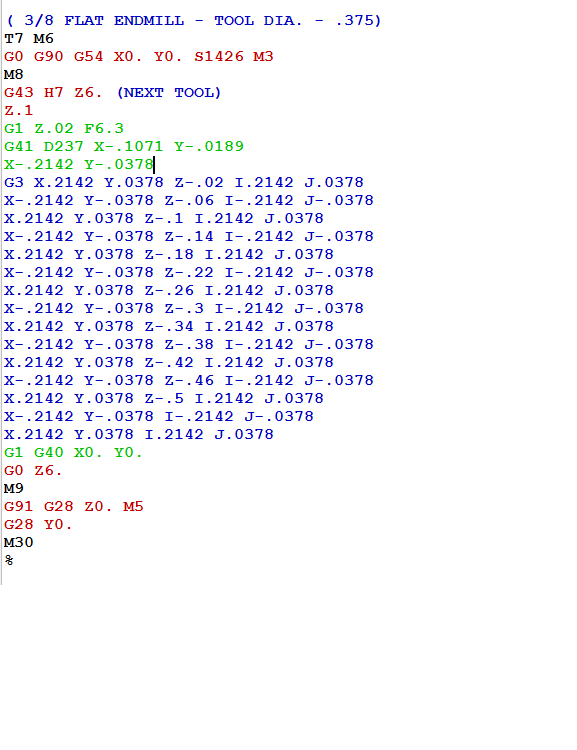
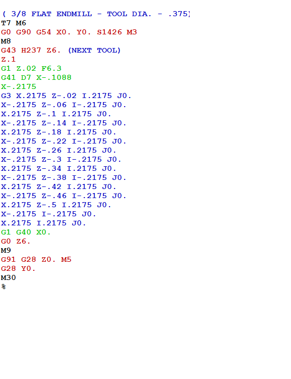
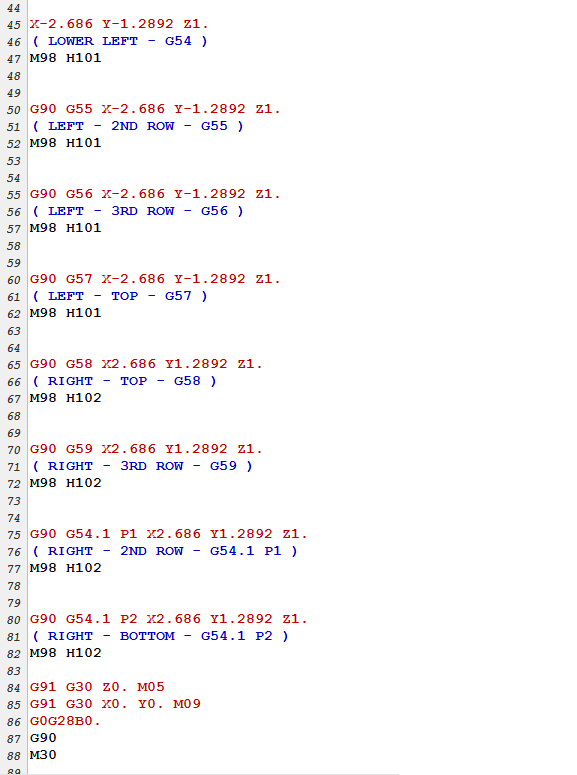
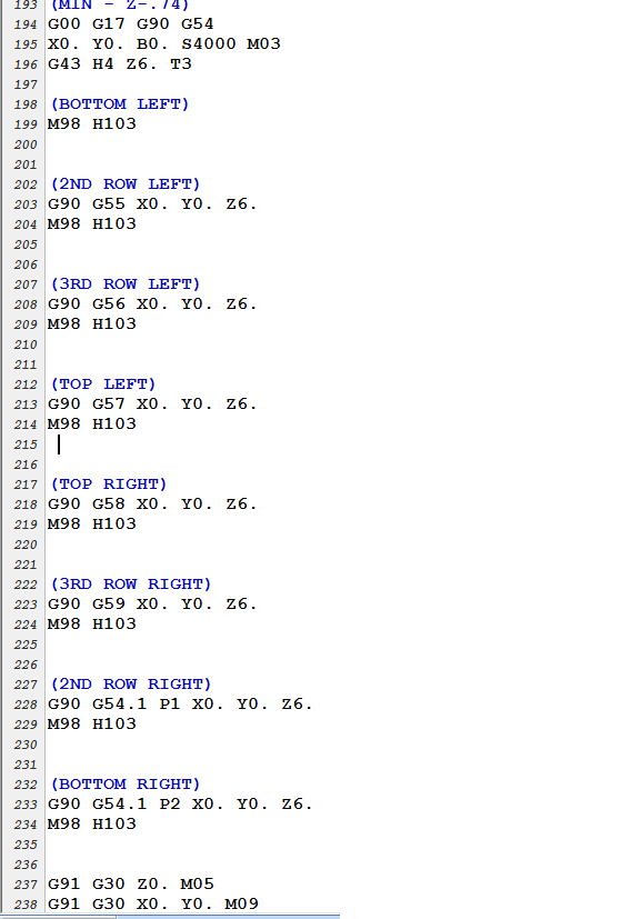
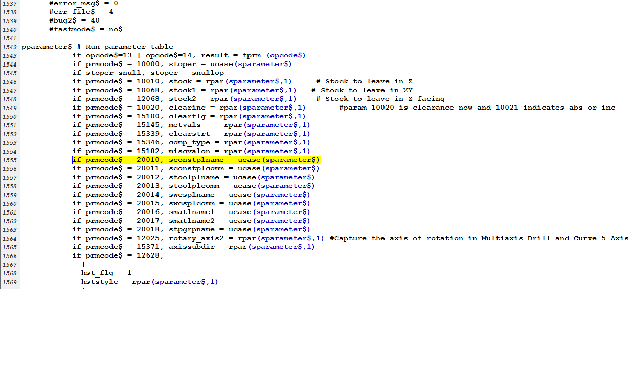
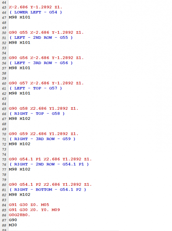
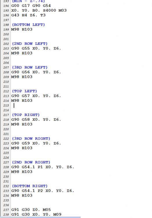
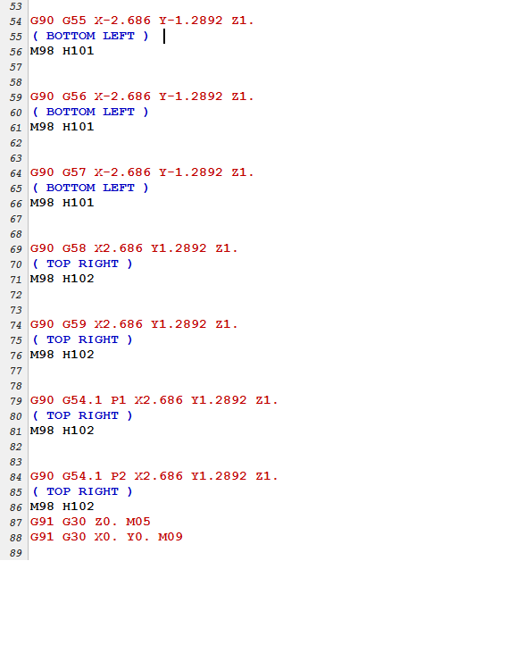
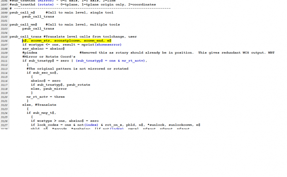
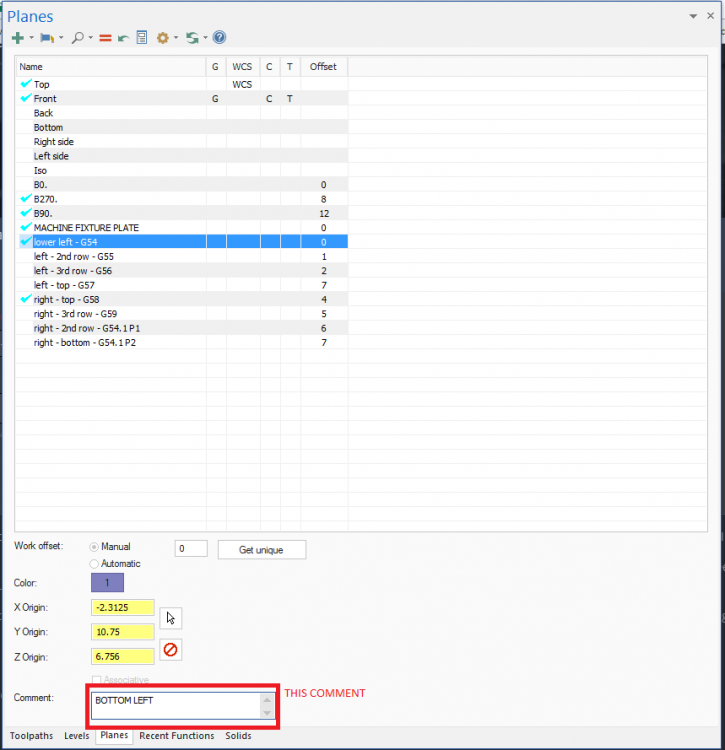
Yeah, I think I got it working, and understand it. I found the code for the tool plane comment - it is 20011. I added it into the post, but it seems I am only getting output from the plane that the original operation is using. Any ideas around that? And actually as I was trying some things as I was doing this post the 20010 prmcode takes the name that you give the plane without needing an additional comment, so I think I will use that. I attached some pics showing the desired output that I hand edited and the current mastercam output, and what I added/am using. Basically I am just trying to label which fixture position is being machined at each sub call.

-
If you change a work offset number in the plane manager and then just repost, does the change show up?
-
Also, is there any way to add logic into the post that would detect that a pre existing plane was not detected if the "match offsets" feature is being used? It would be nice to get an alarm when you post, instead of it just doing whatever.
-
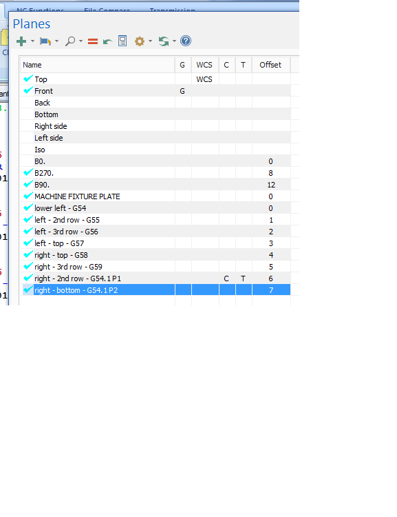
I never noticed until a few weeks ago on the Transform tab the "Match Existing Offsets Stored in Planes". Overall I think it works pretty slick, I like it. 1. Seems that it works the best if the start value for work offset is "0". If the first actual plane being used has, and increment "1". It kind of seemed like those fields should be greyed out if using the match offsets feature. 2. If you change the work offset number of the plane with the planes manager, you need to regen the transform op to get the output to change. This had me chasing my tail a little bit trying to figure out why the match offsets feature didn't appear to be working. Does anyone know what the variable name is for the plane comment?
-
There is also this thread:
-
I really like the offset calculator. I have a spread sheet I use now for jobs with a bunch on angles in them. We find the zero at B0., then I calcualte the other positions. so having a calculator macro the operator could do that all himself, which I would like. So that along with having the ability to easily bolt a fixture on any face and run with changing one number in a program, I think would be worth the time. (and a legitimate chance to get to play with a macro offset calculator. It's been one of my nerd goals for a while) Aaah, I keep thinking a B shift will work and then start thinking about how to do it, but I don't think it will work. You'll run into the same problem I did with G10-ing the B offset. If you rotate 180., the X axis offsets will be flipped flopped. The B shift won't account for that, as far as I know. Feel free to tell me more, because I am interested in different methods to do this. This is just brainstorming phase JParis - We usually run a fixture on the B0 face of both pallets. The offsets are in a header in a G10 block. Those positions are found the 1st time we set the job up. After that you don't need to adjust them much, if at all. So I was thinking since I have those postitions, I could grab them and calculate new offsets for different faces. I would like to get it all to work where the operator types in the B0. faces actual position in one spot at the top of the program, and everything happens automatically from there.
-
Ok, thanks for the replies, I was thinking the answer was going to be needed an offset calculator macro, so I'll go in that direction.
-
What do you guys do to handle bolting fixtures onto different sides of the tombstones? I would like to come up with an easy way to do that that doesn't involve changing the actual machining program. We G10 in all the work coordinates. Usually we just have an Op1 and Op2 fixture on separate pallets and just run one job. Sometimes we set up multiple jobs. So far we've always changed the B positions in the programs. Today I just wrote the B 0 face in the G10 lines, which was B180. today, and then I didn't need to change the B positions in the program, but the rotations X offsets were flip flopped. Which is a workable situation to deal with, but am trying to think what other ways there are to do this?
-
I thought that was going to happen I knew it had to be something. Yeah, it was the edge selection.
-
How do you create curves on solid edges now? It looks like the "Curve One Edge" only does surfaces now?
-
Weird, I started a new file today to play with this some more, and the start angle thing is working...basically. I did that the other day and was having the oddness that I originally posted about. Today putting in a start angle of 0, 90 , 180 , 270 had it starting at the quadrants, except it's rotated by 180 (a start angle of 0 should be at 3 o'clock but it's starting at 9.) Which is odd, but that's fine. It doesn't matter for the machining being done, but looking at the code is a lot easier if the arcs are starting at the quadrants. When I am scanning the code for a program I like to be able to easily figure out what diameter arc is programmed. I started using center points only quite a few years ago, was much more reliable for me, but you do need to enter in the diameter to be machined, which is a source of error. So I like to double check the code to the print. So that's at least why I do that.