


Brian Pallas
-
Posts
183 -
Joined
-
Last visited
-
Days Won
1
Content Type
Profiles
Forums
Downloads
Store
eMastercam Wiki
Blogs
Gallery
Events
Everything posted by Brian Pallas
-
Got 2017 installed, and played around with the stock model on a few jobs now, and adding in the "create lathe stock boundaries" seems to work well and does what I was looking for. Had been using X7, which didn't have that option, that I know of. The new stock model makes it a lot easier
-
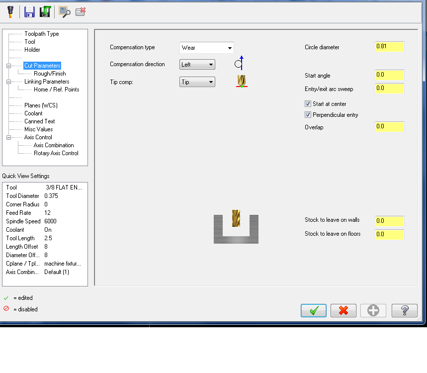
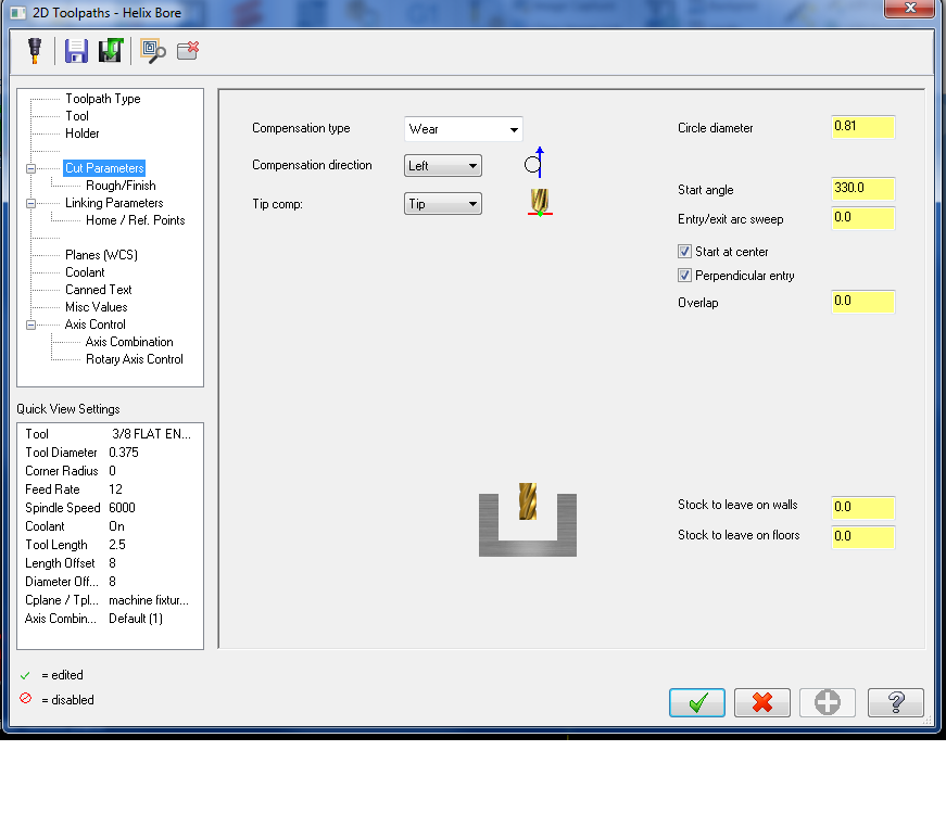
I've noticed before if I use the helix bore with "start angle" and "entry/exit arc sweep" set to 0. (see screenshot 01), that the toolpath isn't starting at an angle of 0. (see screenshot 2). I have to make the start angle different by how much off the tool wants to start, which here is 330. (see screenshot 3), to get it to start at an angle of 0 (screenshot 4). And it doesn't seem to be a constant number that it is off. Changing the pitch on the "rough/finish" tab changes the startpoint of the toolpath also. Never really dug into before why it does that, or how to control the start of the toolpath without playing with the start angle every time. Is there a way to get that to behave appropriately? (the value in the start angle box is the actual value that is used)


-
The "min change in arc plane for helix" setting to .0001 fixed the original problem I was chasing, without causing other side effects that I can tell so far. I uncheked the "truncate" box, back to how it was originally. That caused some other issues to appear in other places. I have not tried using the "arc 3d" chook yet. I didn't see the "round_opt$" variable in the post I am using, so couldn't really play with that on this.
-
It was the control def, had to check the box for "enable staged routines". Thanks
-
Thanks for the replies and suggestions, I am going to have to play around with this some more when I have more time. I already found another issue that popped up from turning the "truncate" box on. So..... we'll see
-
Hello - I have a mpmaster post for a HMC. The next tool was working in X7. After switching to 2017, I wasn't getting any output for the next tool. I put an * in front of the variable, and then it would output, but with T0 all the time. Anyone have any ideas how to fix that? phsm1_on #must remain before G43 pbld, n$, "G43", *tlngno$, pfzout, *next_tool$, e$ pcan2 #Added so M and G codes in canned text will output before phsm2_on phsm2_on #must remain after G43
-
I played around with the "tolerances" and the control def. Not sure if that is what you were referring to. Changing didn't help what I was looking for, but I checked the "truncate" box and that took care of it. Just having mcam cut off everything after the 4th decimal position, instead of rounding anything, Looks like it will work for this, we'll see if it causes any other issues.
-
So I have a toolpath where it is ramping around a slot. Except, for one lap, the code isn't the same. I have full arc moves for everything, but then on one lap, instead of arcs being output, there are lines. Why would it do that on just one lap around, and it isn't the first one or last one? If I output the path with no ramping, it is all arc moves. (SUB H-LIVE - .085 DIA X .010R) M05 M98 P7000 G55 T1515 G17 G98 M245(CONNECT SUB C AXIS) M269 (SUB BRAKE OFF) G0 X1.1113 Y0. Z-1.0 C-45. M8 Z-.1 M268 (SUB BRAKE ON) G97 S6000 M14 (FINISH SLOT) G1 Z.077 F30. X1.095 F10. G3 X.9756 Y.2486 Z.086 R.5475 G2 X.9916 Y.2526 Z.0865 R.0045 Y-.2526 Z.1048 R.5564 X.9756 Y-.2486 Z.1053 R.0045 G3 X1.095 Y0. Z.1143 R.5475 (same corner that gets lines later) X.9756 Y.2486 Z.1233 R.5475 G2 X.9916 Y.2526 Z.1238 R.0045 Y-.2526 Z.1421 R.5564 X.9756 Y-.2486 Z.1426 R.0045 G3 X1.095 Y0. Z.1516 R.5475 X.9756 Y.2486 Z.1607 R.5475 (lines moves here one corner) G1 X.9748 Y.2513 Z.1608 X.9773 Y.2538 Z.1609 X.9823 Y.255 X.9877 Y.2546 Z.161 X.9917 Y.2526 Z.1611 G2 X.9916 Y-.2526 Z.1795 R.5564 X.9756 Y-.2486 Z.18 R.0045 G3 X1.095 Y0. Z.189 R.5475 (here is the same corner again back to an arc move) X.9756 Y.2486 Z.198 R.5475 G2 X.9916 Y.2526 Z.1985 R.0045 Y-.2526 Z.2168 R.5564 X.9756 Y-.2486 Z.2173 R.0045 G3 X1.095 Y0. Z.2263 R.5475 X.9756 Y.2486 Z.2353 R.5475 G2 X.9916 Y.2526 Z.2358 R.0045 X1.077 Y.1402 Z.24 R.5564 X.9916 Y-.2526 R.5565 X.9756 Y-.2486 R.0045 G3 X1.095 Y0. R.5475 X.9756 Y.2486 R.5475 G2 X.9916 Y.2526 R.0045 X1.077 Y.1402 R.5564 G1 X1.0613 Y.1382 G0 Z-.1 Z-1. M9 M05 M246(DISCONNECT SUB C AXIS) M269 (SUB BRAKE OFF) M9 M98 P7000 The time it gets lines, the last endpoint the X is .0001 different than the times it gets arc moves, so maybe that is why it can't put an arc there? But why wouldn't it calculate the positions the same each time? ( Yes, I have too much free time ) slot.pdf
-
2017 - lathe stock update at red arrow
Brian Pallas replied to Brian Pallas's topic in Industrial Forum
Redefining the stock worked -
2017 - lathe stock update at red arrow
Brian Pallas replied to Brian Pallas's topic in Industrial Forum
Not on this file, and the backplot isn't working either, it just shows the finished shape. Same with the lathe stock preview. I made this program, then assigned my work offset numbers, and looks like maybe that boogered up the file? If they didn't change the way those things work. My roughing operations in the program aren't recognizing the stock anymore either. grrrrrrrr. I tried just redoing the roughing ops, that didn't work. Restarted it, that didn't work. I think I am going to be stuck redoing the whole thing. Unless someone knows how to get it unstuck? It's not a big program or anything thankfully. -
I am just starting to use 2017, moving from X7. On the lathe - used to be the stock that is shown changes when you move the red arrow up or down in the operations tree. Now in 2017 it doesn't do that? All it shows is the final stock. Or this an option somewhere that controls how that behaves?
-
For oddball stuff, I always find a diameter close that has the same pitch, and then add or subtract the differences in the nominal size. So I looked in Machinery's Handbook M42 x2 and added 8mm. So minor - 47.835mm-48.210mm
-
Tool management always output H1 and D1
Brian Pallas replied to nickbe10's topic in Post Processor Development Forum
We just got a new HMC with the Celos. They tried telling us the same thing about the H and D numbers. We had them change it so it works normally. So you can do that if you want to go that route. You don't have to use it. Just sayin -
So on jobs on a live tool lathe where I go back and forth between milling and turning, I will use the lathe stock update to get my turned stock, and use that for the start of a stock model for the milling ops as I am working through a program. Is there a way to take that stock model and then use it for the lathe stock without creating a new machine group? I would like to start with my bar stock and then somewhere in the middle of lathe operations, change what is being used as the stock, without affecting the previous lathe operations. Currently I always have to click past a bunch of errors when I regen lathe ops, which always makes me nervous that I might be skipping past an actual problem, and plus the backplot isn't accurate anymore.
-
I've never heard of anything like this happening. R. Van Winkle - Has the machine sat for a period of time after running cast iron? We had some Haas lathes at one shop that ran a production cast iron job like 2-1/2 weeks out of a month, and we eventually got the point where we pulled the chuck and replaced the seals after each run because of contamination. Just wondering if you got to a root cause on why it was rusted in?
-
Sound cool, and something I want to look into. Thanks. What do you pass to the macro - diameter of the bore, diameter of cutter, pitch and depth?
-
Thanks Colin. It's just kind of a "I wonder if..." right now. Sometime here it'll be a good side project to see if I can get it working. Yeah I was wondering about a solution for irregular spacings. One thing I'd like totry for helix boring, or ramping around a contour, is : ( 1/2 FLAT ENDMILL TOOL - 1 DIA. OFF. - 1 LEN. - 1 DIA. - .5 ) G0 G90 X0. Y0. S6000 M3 G43 H1 Z6. M8 Z.1 G1 Z.02 F60. G43 D1 X.375 X.75 M98H1L10 G90 G1 G40 X0. G0 Z6. M5 G00 X0. Y10.M09 M30 N1 G91 G3 X-1.5 Z-.03 I-.75 J0. X1.5 Z-.03 I.75 J0. M99 % So only one lap in the sub and then L count for number of loops. I think I would like to have that option available in mcam , but if I did get something like that able to be output, I would want to come up with a way that verify and backplot in mastercam still works. This is a recent thought, so I'll think about it a bit here and there and then try something.
-
This has been a long time in the pipeline.
Brian Pallas replied to Gracjan aka Pullo's topic in Industrial Forum
That is good. In X7 at least, if you have the solids tree visible, click on the solid in MCAM, then hit "f4", or "Entity Properties" under the "Analyze" menu, that solid in the tree will be highlighted. As far as wireframes - Sounds like you have all your geometry on one level? Each part in an assembly I put the wireframe for that part on it's own level (and I make each part a different color as I'm going), then the solid for it on a level that is 5 higher. And label each level. And use "Level sets" to turn all solids for a design on or off. For a part with a lot of stuff going on I would put the wireframe geometry for each feature, or group of features on a level. I remember when I was learning CAD/CAM in the mold making class at the Community College one of the first things the teacher had me do was take a mold base CAD file, where everything was on one level and go through and put it on different levels and label it. Which taught me 1.Organizing my files and 2. What the parts of a mold base were, because I had to figure out what it was to label it And probably a personal preference of mine, but I will have the fixture design, prints, and part machining program in one file. Then I will "save some" and save the fixture part I need to machine and use a different file for machining the fixture parts. That helped me keep everything simple and easy to find. I had too much stuff going on with everything in one file. When I go to machine a fixture part, I will remove the operation history of the solid. And then you can usually get most of the geometry needed for machining from the geometry that was used to make the solid, but you can change the geometry if needed for machining, without messing up the solid. Plus, for the way I am using it, you would want any design changes done in the design file. -
Is there a way to use the "Helix Bore" toolpath, but have it use a incremental subprogram for each hole in the toolpath? So the tool would move to the hole position, then call the sub, and repeat for each hole? Or are there any other ways to accomplish that fairly easily within mastercam?
-
The machine should be able to read a file structure. Make a folder with the part number. Put your NC programs in the folders. Then you should have a list at the machine in order of part number, with the NC programs in the part folder.
-
G12.1 / Polar Coordinate Interpolation
Brian Pallas replied to Brian Pallas's topic in Industrial Forum
OK, I got it at least functionally working. I created a new variable: polarcoordon : 0 #flag for if G12.1 is on or not Added the flag after turning the polar coordinate mode on or off. pmillccb #Cross/Face canned cycle code, before if interp_flg = 0, [ interp_flg = 1 result = newfs(two, cabs) result = newfs(two, cinc) #Cross/Face canned cycle start code if abs(cuttype) = two, [ #Face canned cycle start code, G112 (break ramp) #Fanuc style uses X diameter, C radius pbld, n$, *sg112, e$ polarcoordon=1 ****************************added this line******* pmillcca #Cross/Face canned cycle code, after #cancel at end of op only regardless of whether or not the next op if interp_flg, [ interp_flg = 0 #Cross/Face canned cycle end code result = newfs(12, cabs) result = newfs(14, cinc) !cabs cabs = 0 if abs(last_cuttype) = two, #Face [ #Fanuc Style pbld, n$, *sg113, e$ polarcoordon = 0 ****************************added this line******* And made a new post block: pcoordretract if polarcoordon = 1, [ pmillcca polarcoordon = 0 ] Inside the " mtlchg0$ #Call from NCI null tool change, mill " block if millcc, [ n$, sgcode, pfxout, pfyout, pfcout, e$ ****************************added this line******* pmillccb #Set mill conversion pcom_moveb ] Then added my new post block to the bottom of "ptoolend" block There isn't any logic to it, it will cancel polar coord mode and reposition the C axis, weather you actually need it or not. And I have the Y axis being output, beacuse I'd like to figure out how to get an alarm/error if the Y is not at zero and the polar coord mode is getting turned on. But for now at least I can see the Y0. at the start of each toolpath and know that that part of it is correct. But this works with the the normal mill contour path. I've haven't spent much time working with them, but I have never used any of the "C-axis paths". I just use the normal milling toolpaths. I tried the C axis face controur as part of trying to get the polar coordinate mode working. It would only post one toolpath. Currently I need to use "force tool change" for that path. Just some more post editing I think. Maybe some time I'll fix that, but like I said, I don't use those toolpaths. But it looks like it works now with the mill contour toolpath at least. I haven't tried it at the machine yet. If anyone has any suggestions about any of this I would like to hear it. Thanks, Brian -
G12.1 / Polar Coordinate Interpolation
Brian Pallas replied to Brian Pallas's topic in Industrial Forum
OK, I read the instructions in the post and each individual path is working correctly. However, when multiple toolpaths in a row are posted there seems to be an issue. Basically, every comment in the program below is a new toolpath, with a new plane created in MCAM. I think I need to cancel Polar Coordinate mode, C index to the start of the next path, then turn Polar Coordinate mode back on. If I post each path individually they come as as needed. Is there a way to get that to work or is that a post edit job? Post version is : V16.00 P4 E1 W16.00 T1400866933 M16.00 I0 O10 ( 3/16 BULL ENDMILL 0.0313 RAD) M05 M98 P7000 G54 T1313 M200 G17 G98 M45(CONNECT C AXIS) M69(C AXIS BRAKE OFF) G0 X1.9075 Y0. Z1. C0. M8 G97 S6000 M13 G12.1 (POLAR COORDINATE INTERPOLATION MODE ON) G1 X1.9075 C0. F500. Z.1 Z-.125 F60. X1.6075 F30. G2 X0. C-.8037 R.8037 X-1.6074 C0. R.8037 X0. C.8037 R.8037 X1.6074 C0. R.8037 G1 X1.9075 Z.1 F500. (FACE OD - CORNER RAD 1) X1.7423 F30. Z-.125 F60. X1.4423 F30. G2 X1.5691 C-.1499 R.2088 X1.5556 C-.2024 R.2088 G1 X1.846 C-.2402 Z.1 F500. (FACE OD - CORNER RAD 2) X1.9075 C0. F30. Z-.125 F60. X1.6075 F30. G2 X1.397 C-.1813 R.2087 G1 X1.5457 C-.3116 Z.1 F500. (FACE OD - CORNER RAD 3) X1.7433 C0. F30. Z-.125 F60. X1.4433 F30. G2 X1.5693 C-.1495 R.2088 X1.556 C-.2019 R.2088 G1 X1.8463 C-.2396 Z.1 F500. (FACE OD - CORNER RAD 4) X1.9075 C0. F30. Z-.125 F60. X1.6075 F30. G2 X1.3958 C-.1816 R.2087 G1 X1.5436 C-.3121 Z.1 F500. Z1. F500. G13.1 (POLAR COORDINATE INTERPOLATION MODE OFF) M05 M46(DISCONNECT C AXIS) M9 -
G12.1 / Polar Coordinate Interpolation
Brian Pallas replied to Brian Pallas's topic in Industrial Forum
I did not follow those instructions. Thanks. I will go through that. -
G12.1 / Polar Coordinate Interpolation
Brian Pallas replied to Brian Pallas's topic in Industrial Forum
No Mazak. They are Mori Seiki NLX lathes. So a mix of the Mitsubishi/ Fanuc controls I think it is on most of them (I think they look the same, but I'm not sure which ones we have) , and then also the Celos controller. -
Hi, I have never used the polar coordinate rotation before. I've been looking at it the last day or so to see if that would be better for us than what we are doing now. The main advantage of it seems to be that there is just the linear feedrate at the beginning of the toolpath with the G12.1, as opposed to all the degree per minute feedrates that are currently in the program. Are there any other advantages of the G12.1 cycle? So, I am trying to understand the output I am getting. Below is a sample code that will mill a 1.42 diameter around a part. Before activating G12.1 the tool is at Y .1474. After the code is activated is the Y ever going to move to 0? If at the machine the tool is going to stay at Y.1474, I don't think that is what I am going to want. I think I want the tool at Y0. At least that is how I have been doing it so far without the polar interpolation. ( 3/16 BULL ENDMILL 0.0313 RAD) M05 M98 P7000 G54 T1313 M200 G17 G98 M45(CONNECT C AXIS) M69(C AXIS BRAKE OFF) G0 X1.8932 Y.1474 Z.1 C0. M8 G97 S6000 M13 G12.1 G1 X1.8932 C.1474 F60. Z-.125 G41 X1.72 C.0974 F30. G3 X1.6074 C0. R.1125 G2 X0. C-.8037 R.8037 X-1.6074 C0. R.8037 X0. C.8037 R.8037 X1.6074 C0. R.8037 X1.6064 C-.03 R.8037 G3 X1.6062 C-.0342 R.1125 X1.7116 C-.1295 R.1125 G1 G40 X1.8809 C-.1826 Z.1 F500. Z1. F500. G13.1 M05 M46(DISCONNECT C AXIS) M9 M98 P7000