CristiP
-
Posts
43 -
Joined
-
Last visited
Content Type
Profiles
Forums
Downloads
Store
eMastercam Wiki
Blogs
Gallery
Events
Everything posted by CristiP
-

Did you know Mastercam has "hidden" 5-axis toolpaths?
CristiP replied to Colin Gilchrist's topic in Industrial Forum
How did you open this? I can't see the content : ( -
Thank you. You are funny. But please if you do not know...stay away.... maybe there are people here who can help me more than you. Your post it doesn't help me.
-
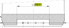
How do I make the tool to cut the red chain and also to be perpendicular to the surface...?? KNURL.MCX-7
-
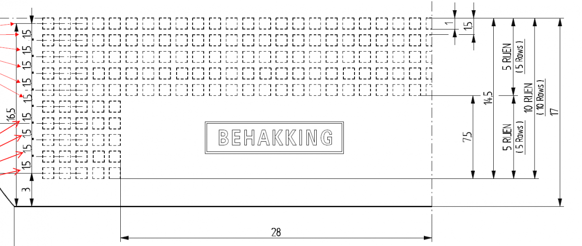
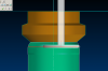
The ideea is to make this with a special tool. The tool is like a T cutter but it has a wheel that rotates around shank. I will position the tool in the mold, I will orient the spindle with M19...the tool will by fixed...I will make each row by pressing the tool in the mold and rotate the mold 360 degrees. Like this the wheel will rotate also..by pressing the whell in the mold and rotate the mold ...it is like a mechanism... Vertical machine: X axis will be 0 Y axis will press into the mold 0.3mm.. Z and A axis for position the mold perpendicular to the T cutter C axis for rotate the mold ...and make the dots I have to find a mastercam toolpath strategy for this Maybe curve 5 axis...I will make a circle around mold where I need firs row of knurling..and I machine that circle with my T cutter perpendicular to the surface in that position.
-
The idea is to make this with a T cutter ....with some kind of wheel with pyramid shape teeth ...without spindle rotation. I will orient the spindle with M19 ...I will position the mold in the right position for one row...and the I will make the dots with my special tool ....by pressing on the mold surface and rotates the mold around tool...like this the wheel it will rotate around shank...I will make some pictures tomorrow. The wheel has 1 degree of freedom ...it can rotate freely around shank ...I have to make this dots by pressing the tool in the mold cavity...and rotate the mold 360 degrees
-
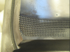
I used M19, tool it is always in the same position, but the table not. The table is moving to get the perpendicular position for each dot.... The mold image I attached it is what I need. That mold was made on a conventional machine. Tomorrow I will make a picture with result of firs method. Imagine the tool stays in the same position but the table it is moving...so the tool can stay perpendicular to the surface for each dot....like this the shape of the dots it is not the same..If for example you look at the first line of my mold picture...each dot it is align with the next one...each row with the next one and so on. ..With the first method...I will get random orientation of dots...
-
Yes I have 2 DMG HSC 55 5 axis machine. Today when I will go to work I will ask my reseller also. I just want a little help from here . I have 5 axis machines I have also Multiaxis on my mastercam licence. I just need an idea to start this . I can give you all information you want ...about my reseller my licence everything...just help me to do this please. More ideas are better than one.
-
Hello guys. I have to make this knurling on the mould cavity. Dots must be perpendicular to the surface. The profile of the knurling dots are shape of pyramid 90 degrees each side ( 4 sides ). First time I used one tool made from a carbide blank with shape of pyramid. I used a drill 5 axis operation with surfaces as tool axis control. With spindle speed turned off I have made the dots. It was fine ...the only problem is that the dots are not oriented in the same way. So now I think I have to use a T cutter for this, but I do not know what mastercam strategy to use. I have to keep this tool perpendiculary to the surface also : ( but I am new to 5 axis machining. I attached a Mastercam X7 file with the profile of the mould in case someone decide to help me with some example. I have also attached some pictures for better understanding. Sorry for my english. Please help me. Please help me. Please help me. Please help me. Please help me. Thanks a lot.. God bless you KNURL.MCX-7
-
new machine VC630/5AX FANUC 31iA5 alot of probleg19
CristiP replied to CristiP's topic in Machining, Tools, Cutting & Probing
Thanks. -
new machine VC630/5AX FANUC 31iA5 alot of probleg19
CristiP replied to CristiP's topic in Machining, Tools, Cutting & Probing
Thank you for your time. I will give you everything you want pictures from the machine,mcx file etc. Tomorrow I will go to work and I'll make some pictures with work offsets, fixtures etc. I do not know what is the line before G68.2. I read something in a Fanuc but alot of thing and short time that is why I need your help. I will try to find and example of program with G68.2 command and more information. Maybe this weekend I will have time to do it. I will take your advice I try to find something helpful here on this forum first. I spoke with my mastercam dealer I wait for his answer. Thank you Crazy^Millman. In the G54 I took the X Y Z coordinates like usualy for setup. I will make some pictures tomorrow. G54.2 it has something to do with this?? Thanks again. Please help me further -
new machine VC630/5AX FANUC 31iA5 alot of probleg19
CristiP replied to CristiP's topic in Machining, Tools, Cutting & Probing
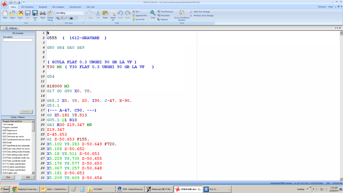
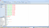
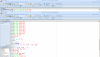
% O555 ( 1612-GRAVARE ) G80 G64 G40 G49 ( SCULA FLAT 0.3 UNGHI 90 GR LA VF ) T30 M6 ( T30 FLAT 0.3 UNGHI 90 GR LA VF ) G54 S18000 M3 G17 G0 G90 X0. Y0. (what means this block before G68.2? Changing this affects the A axis direction A- or A+) G68.2 X0. Y0. Z0. I90. J-47. K-90. (here it supposed to tilt the A axis in minus direction but if the J vector is GT 40 (J-50) A axis it goes in A+ direction where the limit is A+30) G53.1 (--- A-47. C90. ---) G0 X5.181 Y8.513 G05.1 Q1 R10 G43 H30 Z19.347 M8 Z19.347 Testing the G68.2 in A-35 then in A35 with identical toolpaths I saw differences in dephs. One side was deeper. Another thing the tool touches the part with +0.4mm correction on the tool length. Strange. I asked the guys from Doosan about the machine kinematics—they do not know : ( I try to find something in the Fanuc book but a lot of things here. I attached 4 pics with the program (I do not know hot to attach the nc file here), so please take a look. What about the program do you see something wrong making the machine to act like this???? Thanks alot. Any suggestion any ideas I appreciate it.
-
Hello !! Last week we bought a Doosan VC630/5AX with Fanuc 31i. This week I test the postprocesor. At the begining with alot of errors. In the end it works with some adjustements. % O2222 ( DOOSAN TEST PP ) G80 G64 G40 G49 ( FREZA D2/R1---TEST ) T2 M6 ( T2 FREZA D2/R1 ) G54 S12000 M3 G17 G0 G90 X0. Y0. (--- A-3.856 C146.008 ---) G0 X-25.74 Y70.186 G43.4 H2 X-25.74 Y70.186 Z67.724 G0 G90 C146.008 A-3.856 Z67.724 X-22.168 Y75.483 Z-27.061 G1 X-21.98 Y75.762 Z-32.05 F200. X-21.96 Z-32.063 A-3.807 C145.538 F1200. X-21.941 Z-32.076 A-3.758 C145.055 X-21.921 Z-32.089 A-3.71 C144.56 ..... G49 G69 G91 G28 Z0 M5 G28 Y0 M9 G0 G90 A0 C0 (D2/R1) T2 M6 G54 S18000 M3 G17 G0 G90 X0 Y0 G68.2 X0 Y0 Z0 I90 J-35 K-90 G53.1 (--A-35----C90----) G0 X-25.74 Y70.186 G05.1 Q1 G43 H2 Z10 M8 G0 G90 X... Y.... .... G49 G69 G05.1 Q0 G91 G28 Z0 M5 G28 Y0 M9 G90 A0 C0 G0 I have some problems with G68.2. At the begining if it's: G17 G0 G90 X0 Y0 G68.2 X0 Y0 Z0 I90 J-47 K-90 (THIS MEANS A-47 C90)..but the machine it rotates the A axis in + direction (maximum A+ is 30) and it gives me the error with overtravel A axis. If the J is LT 40 (ex: J-40) the A axis position it is ok but if the J is GT 40 (ex: J-47) A axis it goes in A+ where A30 it's the limit...end again Overtravel A axis.. I have tried many options and at the end the working one was: G19 G0 G90 X0 Y0 A-45 C90 (I DO NOT UNDERSTAND WHAT IS THIS) G17 G68.2 X0 Y0 Z0 I90 J-47 K-90 G53.1 G0 X.. Y... G05.1 Q1 G43 H ..... After I finish a bottle cavity in 3 axis only I've made some 3+2---- A35 and A-35 toolpaths to see is the kinematics of the machine it's ok. I've made the toolpaths exactly the same in both sides with the depth of 0.03mm. I first put 0.4mm in tool leght offset because the tool went to deep and second--- depth was different in the two sides. What is happen?? The program for the 2 sides was like this: (D0.6/R0.3) T16 M6 G54 G17 G0 G90 X0 Y0 G68.2 X0 Y0 Z0 I-90 J-35 K90 G53.1 (A-35 C-90) G0 X50 Y50 G05.1 Q1 G43 H16 Z60 M8 Z-20.... ..... G49 G69 G91 G28 Z0 G90 G0 A0 C0 G68.2 X0 Y0 Z0 I90 J-35 K-90 G53.1 X50 Y50 G43 H16 Z60 Z-20.... What is wrong? The guys from doosan they don't know:(. I have also a DMG HSC 55 LINEAR but on this machine we did the kinematics. On Doosan VC630 they say this thing is already did of Doosan from factory. What can be wrong??? Sorry for my english..Please help me...suggestion,ideas Thanks
-
Mastercam X7 MU1 Hotfix released
CristiP replied to Ryan Butt CNC Software's topic in Industrial Forum
good job -
3D model and pencil toolpath=0.3k ?????? why?
CristiP replied to CristiP's topic in Industrial Forum
Yes I see. I have bitangency angle 170 that's why. Offffff I changed everything but not this one. Many thanks Robert -
3D model and pencil toolpath=0.3k ?????? why?
CristiP replied to CristiP's topic in Industrial Forum
nobody wants to help me:( -
or you can play with tools you have in Mastercam, but you will find out that sometimes the results are not quite good. Go to Edit-and the very last 2 option can do the thing.
-
You have a MCX file with the problem...I don't understand what is wrong. Model radius is 1 and I'm using dia3/r1.5. If someone can help me...THANK YOU. PENCIL PROBLEM.MCX-7