


Bill Henderson
-
Posts
260 -
Joined
-
Last visited
Content Type
Profiles
Forums
Downloads
Store
eMastercam Wiki
Blogs
Gallery
Events
Posts posted by Bill Henderson
-
-
Does anyone have access to SAE AS8879 spec sheet?
I have been digging through countless folders searching for ours. I am in a hurry.
Trying to find a minor dia. tolerance for .375-24 thread.
Thanks if anyone has one.
-
Threw me for a second. I thought I posted this and forgot.
Used to be my old handle except smaller case.
-
Can you create a line (2d) from bore one to x0y0 and then from x0y0 to the point?
if so, after that c plane using geometry and pick the lines.
save c plane (remember name)
then if you have to move it use xform translate between views. from the one you created to the top or side or whatever.
not sure if x5 had the dynamic wcs yet or not. otherwise just use that.
-
Same here. about 3-4 minutes
-
got it.
make true threads works.
-
Good morning,
quick question.
First of all I am not a lathe programmer.
I was wondering about verify and how accurate it is to a stock model.
The program was written by our lathe programmer.
I took my gage (part with acme thread) and made that the stock model in verify. when i run it the threads never match my stock model. it is supposed to be a 4.233 TPI (single start) I have tried moving the start position back and forth within a range of .236/4 (90 degrees) and it doesn't work.
Should it match up?
I looked at the code and the feeds and speeds are correct. I changed the start point with out a lead just to see if it was right.
Driving me insane.
Any help is greatly appreciated.
-
Yes on a live tooling lathe.
I agree the mill is better.
The tolerance is a length from a datum to a point on the thread at a given angle.
Military application is all I can say.
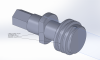
My image shows a gage we are trying to make to check our part before sending it in for qualification.
The gage used by the customer is the only one they have and about 20K plus 8 wks for one to be made.
-
Bump...
The tolerance we need to hold is +/-.001 on the ACME and +/-.0007 on the fine thread (not shown).
Lead time on getting a gage made is far too long, so we are trying this ourselves.
-
I am not a lathe guy and our lathe programmer is fairly new to MC.
He is using a HAAS.
If I have a critical timed point on a thread and it is timed dimensionally to a flat on the part can this be achieved in MC? or the HAAS for that matter.
He seems to think the threading starts at a dimension he gives it regardless of spindle orientation.
Thanks for any input.
-
Wear also allows a verify because MC will be using the diameter of the tool used. (have they changed this yet?)
Some places that use alot of regrinds will sometimes use a probe for tool dia. Leaving it at control gives the operator a chance to use alternate tooling if need be because the code is posted to the arc size. The tool table needs a tool dia./radius.
Posting to wear will give you a verify that is "accurate" but in some instances give you errors with too large or small lead-ins. at the machine
-
thanks guys. you may be onto something Matthew
-
I have a question regarding this female thread callout.
Print specifies a clocked 6 pitch left hand thread. 29 degrees so I am assuming ACME. Pitch diameter is 1.273.
The model however when you measure the pitch shows .236 instead of a 6 pitch (.1666)
Not too familiar with the thread.
Reading about multiple starts etc... could this be the reason possibly for the .236?
It is a military application btw.
Any insight would be greatly appreciated.
Thank you
-
If your machine is capable of IJK instead of Q.
Pick your rapid plane as you did the for the first drill and use the decreasing peck. Make your first peck the distance of the first hole drilled. (I). then the decrease (j) and finally a peck value (k).
If (i) is 1.00 and you want to peck .05 the (j) would .950 and (k) is .05
-
Super. Thanks Wes and john.
Worked great.
-
I will try it thank you both.
-
Rotating along Y is what I meant to say Wes.
No we don't.
-
This is probably really simple, but I have never had to program on a rotary before.
Part will sit axis on X. Rotating about Y.
If I wanted to cut a helix 1/4 inch per revolution along X... How would I do it?
I have a HAAS. I have the rotary and A enabled on my machine def.
When I go to a 2d contour and go to the axis page what should my settings be? 3 axis?
Should verify show the helix cut? Shows just a straight slot as it sits now.
Is there another setting I need changed to get the rotation about X? Is that A(0.)
I'd really like to learn this stuff.
Any help is appreciated.
-
I remember using Cimco (paid for trial version) a few times. Anyone else use it and compare to actual cycle times at the machine?
I did on a long multi surf, multi tool and drill cut and it was fairly accurate. Machine time was like 18 hours... ended up being within about ten minutes. (Set my alarm to head into the shop in the middle of the night)
If Cimco turned out to be accurate you'd have to manually enter the comment though.
-
We were just talking about this this morning here...
I always have left them in, but here for memory reasons they asked for them to be removed.
You see after they get the candles burning, squirrels turning the generators, and the woodstove to get the nip out of the shop I actually have to use those new fangled things called 1.44 diskettes to send my programs to the machine... and if I am lucky and they are not over 400k in most instances the machine can take it into memory.
Those are joyous times... when cutter comp can be anywhere in the program and its easy breazy to search and adjust.
-
Is it a 3d type undercut?
If it's not I would suggest just using a 2d contour arcing on and off with enough clearance.
-
Better safe than... oops...should've double checked... Sorry.

-
How do you mean? Using a server for the "shop's" libraries, or keeping it on individual workstations?
-
When you are creating electrodes... I assume you are keeping the original in burn location and rotating copy that into a new plane (most likely origin top view).
What I had found with cores or cavities with lots of electrodes.. I created them in burn location and then turned off core or cavity and file save some picking only my electrodes. When it came time to cut I used the WCS so I never had to transform the trodes.
What seems to happen especially when making trodes is you get trimmed sheets. When you copy the blank sheets start multiplying for every copy rotate translate what have you.
Large files after the electrodes are made use save some, the blanked entities get cleaned up. If you need to keep the electrode cut files with the original model try (save first) to turn on all levels and screen unblank unblank all and delete non associated entities.
Typically I will turn the models I need to one specific color and level and the blanks to another color/level ( it can be quite messy depending on slab surfaces count and size).
That should really help in downsizing the memory.
Kind of why I started designing my electrodes in UG or the design side software. Try to keep my mastercam cut files as small as possible.
-
I did see that. I downloaded it and I quickly tried it. I could not get it work properly. I think its because I use cimco edit for my editor not the mastercam editor, not sure.
I confess I didn't spend too much time on it. We've been using the no frills stuff since around v8 or so.
I did try active editor. Spent about a day an half on it when we were slow and I could not get it right like you and went back to the "old" way.
Correct. The one shown above is html format.

Standards
in Industrial Forum
Posted
I found a mil s 8879 on hand.
Why do they make it so complicated.