


dmaier
-
Posts
71 -
Joined
-
Last visited
Content Type
Profiles
Forums
Downloads
Store
eMastercam Wiki
Blogs
Gallery
Events
Everything posted by dmaier
-
Never mind got it working. I thought leaving the values blank in the MD was to display the default on/off instead of the custom code displaying inside the tool path parameters when selecting a coolant option. I had it reversed. I set my strings back to just quotations. Displaying on/off/ignore would be nice because we have a lot of custom coolant code here and not having to memorize if they are an on or off command would of been nice.
-
Editing MPMASTER post. I would like to use the X style coolant to allow all the coolant options being used on our machines. Below are the M codes I want to output in my post. I have a screenshot of my Machine Definition's coolant commands tab. I am not getting any M codes to post. What am I doing wrong? I thought the instructions for this seemed pretty straight forward but I must be a little backwards. # Coolant output code selection for X style coolant # Note: To enable X style coolant, click on the General Machine Parameters icon # in the Machine Definition Manager, Coolant tab, disable first check box # Output of X style coolant commands in this post is controlled by pcan, pcan1, & pcan2 # This string select is setup using the "Coolant Commands" tab in the "General Machine Parameters" scool50 : "M08" #Coolant 1 on value scool51 : "M09" #Coolant 1 off value scool52 : "M07" #Coolant 2 on value scool53 : "M09" #Coolant 2 off value scool54 : "M07" #Coolant 3 on value scool55 : "M09" #Coolant 3 off value scool56 : "M50" #Coolant 4 on value scool57 : "M09" #Coolant 4 off value scool58 : "" #Coolant 5 on value scool59 : "" #Coolant 5 off value scool60 : "" #Coolant 6 on value scool61 : "" #Coolant 6 off value scool62 : "" #Coolant 7 on value scool63 : "" #Coolant 7 off value scool64 : "" #Coolant 8 on value scool65 : "" #Coolant 8 off value scool66 : "" #Coolant 9 on value scool67 : "" #Coolant 9 off value scool68 : "" #Coolant 10 on value scool69 : "" #Coolant 10 off value scoolantx : "" #Target for string

-
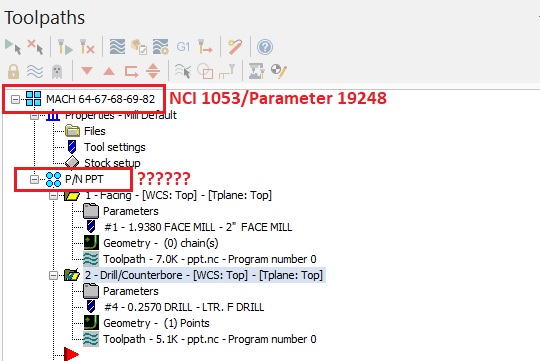
I have the lasted MPFAN post v20.00. Unless I am miss understanding the NCI 1051-1054 values, the red box with the question marks is the information I am trying to add as a comment. I just finished looking through the parameters pdf with no luck.
-
NCI 1051-1054 did not have any info for Tool Group Name. I was able to find a parameter number (19248) for Machine Group Name in the parameters guide to match NCI 1053. Still looking to get the Tool Group Name. Worse case senerio I will just put the Info I desire from the tool group name into the machine group comment section. Its an extra click or two but I do have a parameter number for that as well (19111). I did play with checking the box in control definition to enable machine group name comments but that was posting in my gcode more than I wanted. For the format I am looking to have, I want this info posted once in the comment section of the pheader$. Will give an update if I do find the parameter number. Still looking.
-
I am looking for the parameter for the toolpath group as well as the machine group parameter. I am going through the reference guide right now and haven't found anything doing a electronic search. I will be going through the 296 pages in the "Operations Parameter Referance" to find them. I will post an update on what I find.
-
Length/Diameter geometry offsets is what would be collected. We have dedicated tools that are not to be broken down for each job. This is more for archiving purposes vs re-entering previous values back into the machine when the program is ran. We would like to have the data for when a old job is set up for a new run. If we are having tolerance issues we would like to compare data from a good run to the problem run to eliminate any tooling issues (IE: deflection from a tool being longer than the last run)
-
Ethernet. If saving to a separate file is easier I'm sure he would be fine with that too. He is looking for a way automate operation records like you suggested and eliminate hard to read penmanship and incorrectly recorded information by an operator. I will look into the book you suggested. All the sites I have been to so far have been recommending "CNC Programming using Fanuc Custom Macro B" by S.K. Sinha. I was going to look into that book as well. Seen an online class certified by Fanuc on CNC Concept Inc's webpage. I already sent an email to them for more information about the class. They seemed pretty reasonable in price compared to the in-person class Fanuc offers.
-
I do not know anything about parametric programming other than what I have researched today. My boss would like the tool offset data used during a program run from a machine to be saved in our .nc program before it is sent back to our server. Is this is possible? I have not found any reference about saving machine parameter data back into a .nc program but have found references stating anything is possible with parametric programming. Does this fall into the "anything is possible" category? We work with Fanuc controllers in our shop. I think I would be dealing with Macro B programming if I understand what I read earlier correctly. If this is possible I will look for some classes to better understand this programming method.
-
Adding work offset to sequence number.
dmaier replied to dmaier's topic in Post Processor Development Forum
I am not sure if this would of effected my WCS output so I changed and added a 1 to the g_wcs and p_wcs. I took and modified the pwcs post block to help with the format the sequence numbers. I have the outcome I was looking for. Was I correct by redefining g_wcs to g_wcs1 or did I just create more lines than necessary in my post? I am still trying to get the hang of this and want to keep the code as clean as possible. #Sequence number format op_num0 : 0 #Format statement for G54 WCS Operation Number Variable op_num1 : 0 #Format statement for G54.X WCS Operation Number Variable pseqnum : 0 #Format statement for sequence number post block Variable fmt " " 4 pseqnum #Format statement for sequence number post block fmt "N" 4 g_wcs1 #Format statement for G54 WCS fmt "" 4 p_wcs1 #Format statement for G54.X WCS fmt "" 4 op_num0 #Format statement for G54 WCS Operation Numbers fmt "" 4 op_num1 #Format statement for G54.X WCS Operation Numbers op_num0 = opinfo(15240, 0) * 100 op_num1 = opinfo(15240, 0) * 1000 pseqnum #G54+ coordinate settings for sequence numbers [ if workofs$ < 6, [ g_wcs1 = op_num0 + workofs$ + 54 *g_wcs1 ] else, [ p_wcs1 = (op_num1) + (54 * 10) + (workofs$ - five) "N", *p_wcs1 ] ] -
Adding work offset to sequence number.
dmaier replied to dmaier's topic in Post Processor Development Forum
Thank you for the input. I appreciate any piece of information shared. This week I feel I have learned a lot and not enough at the same time about Mastercam posts. -
Adding work offset to sequence number.
dmaier replied to dmaier's topic in Post Processor Development Forum
I finally got the output I was looking for. Created the block below and inserted "op_num" into blocks psof$, ptlch$, and ptlch0$. #Format sequence number variables op_num : 0 fmt "N" 4 op_num g_wcs = workofs$ + 54 op_num = opinfo(15240, 0) * 100 + g_wcs I could not get any work offset data out of the p_wcs so I stuck with g_wcs string. Is there something I need to do to pull information from p_wcs? -
Adding work offset to sequence number.
dmaier replied to dmaier's topic in Post Processor Development Forum
I originally was using the p_wcs string in place of workofs$ with no output recognition. I switched to the g_wcs string and was able to get my offset number to show correctly but it was resetting my count after 5 sequence numbers. I changed the seqinc$ string to op_id$. That doubled my count of the 5th sequence number output. Using workofs$ did not alter my sequence number count, but did not modify the offset number after the first sequence number. I am going to start trying these combinations in different locations now. I had been inserting this code in the psof0$ section of the post. -
Adding work offset to sequence number.
dmaier replied to dmaier's topic in Post Processor Development Forum
n$ = seqinc$ + workofs$ Is there a different string to be using besides "workofs$" I am getting the format I want but it will only use the work offset number from the first sequence number and not the current work offset number. -
Adding work offset to sequence number.
dmaier replied to dmaier's topic in Post Processor Development Forum
Thank you, I will try doing that. -
I am modifying the MPFAN post to allow sequence numbers to show only on tool and work offsets changes. I have accomplished that part with my sequence numbers increasing by 1. I would like for the work offset number to follow my sequence number (IE n154, n254, n354, n455, n554). Any suggestions on how to insert the work offset number to follow behind my sequence number?
-
The part will be ran in separate mill and lathe machines. I created the plane "Lathe" because the default planes that came in with my machine group were not in the location I desired. The created plane is based off the stock geometry I have drawn and clearance of the part. I removed the original solid geometry and replaced it with a generic solid in the same plane the original solid was imported in. I hope this doesn't create an issue. I also am aware that the geometry for the tool I am creating is not oriented correctly but I left it as is from my first screen shot. sample.ZIP
-
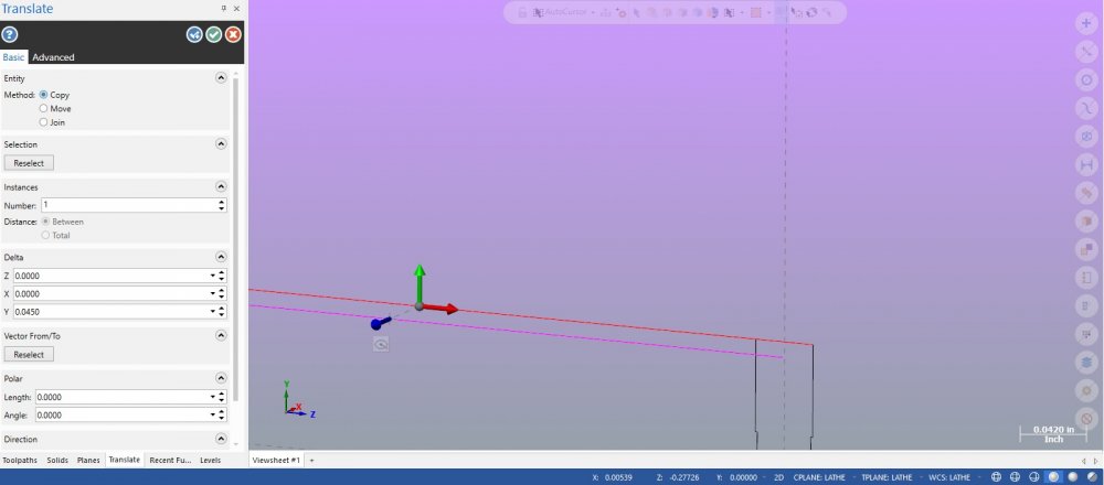
When I translate an entity I do not understand the logic with the gnome. On the screen I see the green arrow for "Y" pointing straight up on both the lower left hand corner gnome and the temporary gnome by the entity I am looking to move. Why is it that if I drag the green "Y" arrow up it will move my entity up and down like I want to do but if I type the distance in the Delta box it moves in a different direction. I am only a few months in using Mastercam and have taken some online training courses but either missed the logic of this feature or I did not understand it correctly when it was explained. Can someone please shed some light on what I am not doing correctly to prevent guessing which "X,Y,Z" box I need to type in to move my entity the right direction. Are the red blue green colors of the arrow not linked to X,Y,and Z?
-
VERISURF TOOLS For MASTERCAM 2024
dmaier replied to Verisurf - Ernie Husted's topic in Industrial Forum
Same here. I tried yesterday and today. Nothing. -
Using different cad software is not an option at this point. I would prefer to use Creo for all my design (mostly because I have several years of design and toolpath creation with it). My new employer wants to use Mastercam exclusively and I am open-minded enough to switch to what the company wants. Just figured that being new to the software that someone might have some insight or trick on how to create a sectional view of multiple solids more efficient than what I am able to currently do.
-
I am new to Mastercam and have just a few months experience using it. The previous several years I was using PTC Wildfire and Creo. With PTC I was able to create a sectional view using a plane within an assembly. I tried using "Trim by plane" in the "Solids" tabs under "modify". Worked great for a single solid. I do not want to Boolean my solids into one because each solid is an individual part making an assembly. Is there a way to perform a "Trim by plane" on several solids at a time or do I have to perform this action on each individual solid.

