LucasGC
-
Posts
146 -
Joined
-
Last visited
Content Type
Profiles
Forums
Downloads
Store
eMastercam Wiki
Blogs
Gallery
Events
Everything posted by LucasGC
-
Actually I think this might be the same problem I had when I originally switched from metric to standard. I programmed a part in metric the same way i did a part in standard and the standard came out much smoother. I think I will just try and remake this and see if it fixes it.
-
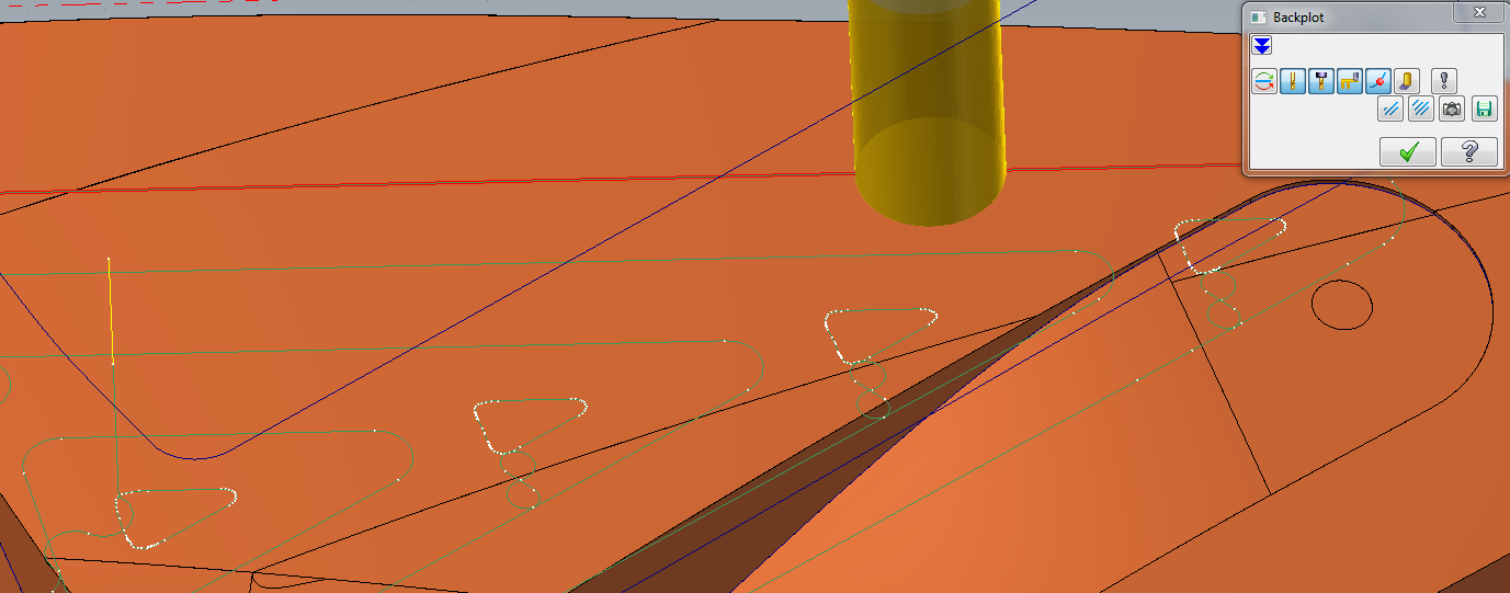
Hi all. I'm sure this is something I've struggled with before and I'm not sure what's different. I have a simple roughing toolpath and it bounces around going through small geometry. I'm thinking this is mostly because of the tangency factor on thermwood machines, but i'm hoping not. Is this a common occurance? is my part geometry just wack? I've tried scallop, hybrid, and pencil finishing toolpaths, all come out with pock marks all over the piece. Even during rough pocket cut it will bounce around. pock.nc pock.mcam IMG_0903.3gp


-
Think I've almost got it with loft if loft didn't try and go node to node.............
-
Is there a way to make a surface from just a grid without boundary?
-
Working on creating a new surface, looking for ideas on how to do this. First try I'm selecting the surface boundary, then creating a flat plane on my tplane a using curve flowline to make a .1 grid, then projecting it onto my surfaces and then hiding the surface so now I have a grid flowline and my outer boundary. Now I plan on using net somehow
-
Hello, I'm having difficulty with the swarf mill toolpath again. This is very frustrating. One thing I'm thinking is going wrong is that I'm using multiple surfaces, all of which can be extended smoothly, but when I try and make the flowline on them I have to switch between u and v to get the lines to travel the same direction. My thought is the swarf is looking at this the same way where it is looking at some surfaces as vertical and some as horizontal. Is there a way to rotate a surface or something that will let me switch my u and v on a surface? Thanks
-
any way to manually arrange? like rotate it the way you want it, drag to a corner, drag the next piece close to where you want it and hit okay - then it would tighten it up. ideally
-
Any input on optimizing this nesting operation? I can get my parts to fit if I use horizontal fill, but when i select calculate it can't fit all the parts. Are there options for the way that it calculates this? Went from 90 degree step angle to 45, fit less parts than with 90 even though it has more to work with....
-
5ax multisurf check surface leaves too much stock
LucasGC replied to LucasGC's topic in Industrial Forum
Has anyone experienced this? Now becoming a recurring problem adding .01 corner radius to tool fixes it. -
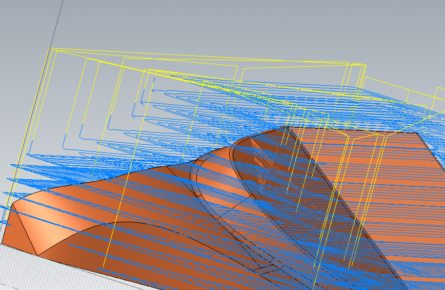
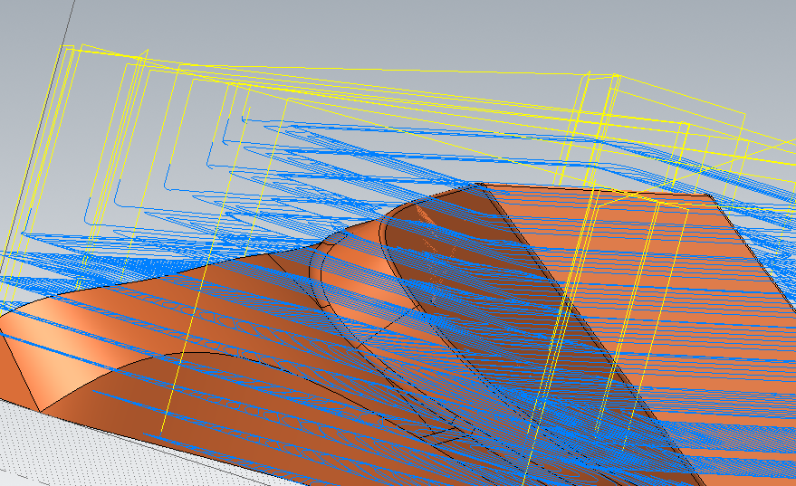
Hello, Using this operation for a while and have noticed this problem with check surfaces before. Whenever I apply it leaves a lot of space before it gets to the check surface. I thought this was because the length of the surface didn't match the stepover size, but when I remove check surface I can put in any value for stepover and it will start and end at exact surface edges. This is all geometry I've created on my own, very basic, very clean. Sometimes I have this problem sometimes I don't. I could use another toolpath but I can get the results I want with the least amount of clicks with this toolpath I think so I would like to figure it out. Any help is appreciated! trim cutting temp new.mcam
-
Ugh, that's it. Thanks! Thought I had found all the config areas but missed the main one...
-
Still having this problem - bunch of different parts now but none of them have cut lines that are touching or even close. all parts have a little stock around them still. It's like it's including the toolpath in the part size
-
I definitely have a lot to learn... I'm finally happy with the way my machine is running, I do feel like I'm starting at the basics again but even the basics now are better than what I was doing. However this part i'm working with really does have a lot of small surface gaps, they're smaller than the tool but still might throw the geometry off a little. It looks like Frankenstein surfaces. I'm just trying to find a workaround for this tangency factor. I still don't know how it works, i have this theory. I think the smaller detailed parts you are cutting you would want smaller tangency, or else it would jump into the corner and jump out. for larger parts you'd want high tangency so that it doesn't slow down around curves. you could change it between every toolpath but you couldn't run any with small geometry and large geometry in the same toolpath. default 1 seems to work fine on small and large parts, but I wanted to try the filter settings to see what effect it would have on tangency factor. Really still trying to figure out what filtering does. if i have .005 overall and 10% cut tol, 90% filter, (.0005, .0045) does that mean it will generate a .0005 cut tol toolpath, and then remove all of the line segments smaller than .0045" ? If I am using .005 overall, 10% cut, 90% smoothing does that mean it will put... tangent arcs? that runs through the 10% generated points to make an arc with a .0045 length? I think this is wrong
-
nope, switched to standard :/ so .0005 overall is what i'm used to using, with 10% cut tol
-
okay if i change it to anything smaller than .00125 it does not regenerate my toolpath chaining tol is .001, would this make a difference? haven't run into this before changed chaining tol, nothing
-
hey friends. I've hit a little snag. I have a scallop toolpath that I'm happy with, but i've programmed it with .005 overall tolerance so that it would regen quickly as I was changing other options. Now when I go to change the tolerance, i only turn on smoothing 90%, and set cut tol to 10%. When i regen this it regens quickly but there is no toolpath. verify will say please select at least one operation to run
-
My default chaining tolerance was too high, sorry. able to spline from curves and refit. Fixed, can i delete my own post?
-
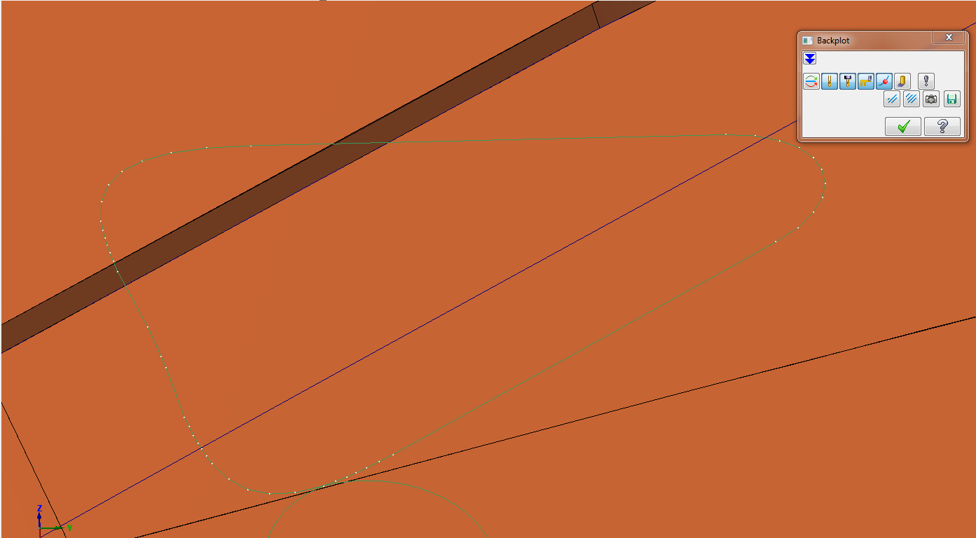
I made a silhouette boundary and when I try and shift click it won't select the entire chain. There is a line that it stops at that looks like it's connected to the rest. I've tried deleting it and creating another line between the two endpoints, still doesn't recognize as chain. The weird thing is if I delete this line and then shift click my chain, it selects the entire chain even though there is a gap where that line was. Anyone else had this problem? I've tried shutting down / restarting.
-
Hi friends. I finally figured out the cause of the jittery motions I've been seeing on my machine and I feel so so so dumb for not fixing it earlier. I wasted so so so much time. so so so awful. I had my tangency factor set too high. I remember seeing a recommendation to use it at somewhere between 5 and 10, so I had defaulted mine to 8 and I figured I would just be able to make a toolpath that would work with this value. I did ask Thermwood "is there a drawback to using max tangency other than tolerance deviation?" and got the response "there is no other drawback to having a high tangency besides the deviation. What you are seeing in your videos most likely is the control Starving for motion because your segments are too small." This led me to believe that the higher tangency value I had, the smoother my toolpath would be. So that's a little frustrating. Oh well. Programming with my tangency now set to 1 seems to be working just fine. Every once in a while I will see it make a strange step but MUCH less frequently and MUCH less drastic. There is no option to turn off the tangency factor, deleting the code still defaults it to 1. The smallest value you can go to is .1 but there is no way of knowing what this value actually means since the equation is proprietary so I think i will just stick to default 1. I also think there is a problem in Mcam between metric and standard processing of high-speed toolpaths. I've had two operations, a 3d hybrid and a 3d pocket high speed strategy, that I've made on the same part in both metric and standard files, and tried to make them as equal as possible (same surfaces, boundaries, tolerances) and kept coming up with more total moves in my metric operation than in my standard. I've brought this up to mcam support but since I've switched to programming in standard and have not pressed them further, I don't think they pursued it.
- 1 reply
-
- 3
-

-
Okay, that does make sense. I should have tried 0 but I figured it would be the same as selecting 'use as computed' Would you also be able to just tell it that you're using a ball nose that's the same diameter and then use that radius? I guess this way you would only be able to put a distance of half your tool radius, and using with a path you can set it to any distance? Thanks
-
Hi - using optirest with stock file trying to ignore small cusps i get the error "optirest not supported when negative stock adjustment is larger than tool corner radius and single stock file is selected" I've tried putting large and small values in the 'adjustment to stock' distance box. I'm just not really sure what this is saying, do I need to change a value in my cut parameters?
-
Hello, I have the same part that I'm nesting on a sheet, and where it says part-distance I have it set at zero. I also have the optimized pairs and combine cuts enabled. There is still a big clearance between the parts. I either want to get this smaller, or to where the lines will actually overlap. (just a contour path with one tool) I've tried putting a negative number in the part spacing box but it will not let me. Any help is appreciated! Thanks
-
I'm using the dynamic optirest and when I use the steep/shallow z-depths (stopping at .25 stock) I have to put the top limit above where I want the first cut, or else it will make my toolpaths go around some sort of internal boundary. I can make it go above by one pass and it will take away all the material I need, but i have that first air pass. Taking it down adds gaps to my toolpaths. Anyone else had this problem?
-
I don't think i ever posted on how I fixed this issue. I don't know if I necessarily fixed it or just got around it. It was mostly the last two passes that were very jagged, so i moved the boundary inwards two steps worth... those extra two passes would have been nice just to verify that nothing had been left but i think without them the path is ending on the exact surface edges. The last pass is still wavy but significantly better and able to be smoothed through filtering
-
I guess I was giving the machine an unrealistic feedrate, and then thinking the tolerance would just keep it at the max feedrate it could handle. Can the machine calculate feedrate based on look ahead or is it per line segment?