


LucasGC
-
Posts
146 -
Joined
-
Last visited
Content Type
Profiles
Forums
Downloads
Store
eMastercam Wiki
Blogs
Gallery
Events
Everything posted by LucasGC
-
Dang, yeah I did notice the surface is wavy if it's extended :/ Have tried a bunch of lines types but I will keep trying! Wondering why it's wavy in the first place. Just not created well or conflicts between programs?
-
Oh, I thought I was just worried about them having too many. How would I get them to have the same number of points if they are different curves though? I mean wouldn't different geometry need different points? This is also a problem for me when I try lofting surfaces, and I don't have splines with the same start point, the surface gets all twisty.
-
lol running with auto control strat:
-
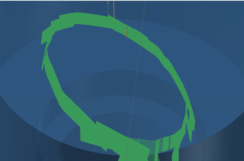
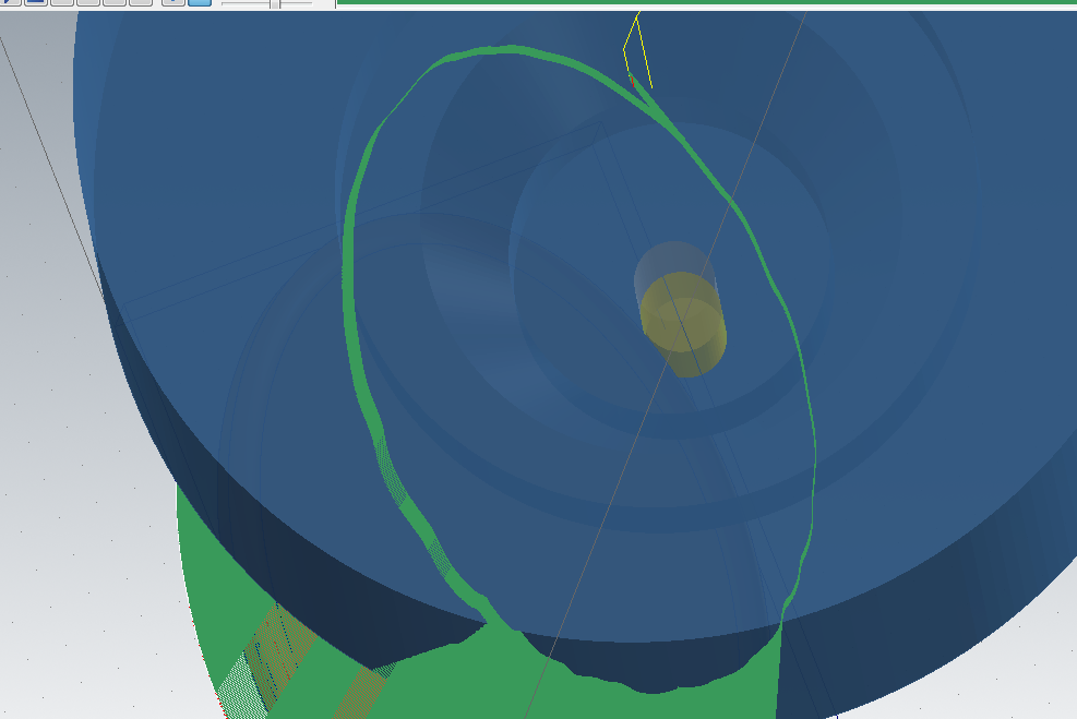
Okay, yes i think i could tilt it, i don't mind the retract, i would rather figure it out this way than tilting all the parts I need to run swarf on :/ Running the swarf with .06" angle inc seems a little worse, ha. But I do see the wavy vectors in backplot, so It should just be something I need to tweak. Posting a pic of the vectors, seems decent to me, definitely wavy, but smooth wavy. Not sure what else to do with my geometry to get a smoother path. TOP.mcam
-
I'm excited to get to point and click programming... just so satisfying to see a perfect part. I wasn't trying to run too fast, 300ipm. Now I've bumped it down to 100ipm, and it is a better. What's your favorite way to recreate surfaces? I have one surface that has a lot of boundary points, i've tried curving the edges, refitting, untrimming original surface, and trimming back down to refitted splines, but still similar amount of boundary points. Then I used create flowline to create two u lines and two v lines, made a net surface from those, extended (was just a little off original surface) and then trimmed to boundary, still had similar boundary points. Tip from thermwood was to set tol to .0005 for true 5-ax ops and .06" for max angle change. Haven't found the difference between max angle change in tool axis control tab vs misc tab. it does retract, is that what you mean?
-
Awesome, appreciate it. Also, I wasn't able to open your file, 'sim not enabled for necessary product'. But I'm on to an even simpler part, have recreated the surfaces and curves, still jittery on the swarf toolpath though. Tried decreasing my feedrate, that helped a little but i feel like this shouldn't be what i need to do - the machine should be able to cut as fast as the tool can handle, yes? 1.mcam
-
Hi. sorry, that post was not about my problem I accidentally posted it. But grr, i do anger toward swarf. lol. I've just kind of been playing with settings without knowing what they do, but I feel like with as much as I've messed around with them, I am still not closer to getting a smooth cut. I switched to 3d curve with a chain as the guide and it works pretty well, feel like I could get it closer than I could with the swarf. I don't know if this is a machine problem because it looks pretty smooth in mastercam in backplot, but when I run it it's got some pretty big steps that I can't see in mcam. I'm trying to make this with as much code as I can, thinking it will make it run smoother on a thermwood router. So this is what I've done: Created untrimmed surface, offset the top rail 2 inches above bottom rail instead of only being .25 above. tried converting rails into lines/arcs, didn't see a difference, went back to 'curved edges' with 1 degree break tol. Have played with max step and tolerance values. tried tolerance at .01,.001,.0001 with max step at .001. I think it performed best at .01, but had one bigger step in it, .001 did fine and i'm thinking is what I will use if I can figure out how else to smooth it, .0001 was too slow and still jerky. I prefer the cut strategy to sync with main axis, keeps it straight better. Honestly I feel like there's so many settings that could be changed that I'm not going to find the 'one' that is wrong. I heard that thermwood machines like a ton of code, so I'm trying to make a toolpath with only line geometry bunch of questions/things I think I might have correct: my max angle step is 1, and I have minimize rotation checked, why would you not check this? none of my 'adjust feedrate' boxes are checked in utility tab - if I have points at a set distance then feedrate should be pretty consistent, yes? in the misc tab there is a box for max angle step for rotation axis that I don't have checked. Recommended? BASE.mcam
-
Hi all, Anyone know how to do this with multi passes? The linking page
-
Hi all, Ran a finish hybrid toolpath over a part with a 6mm ball nose end mill, now I'm trying to use finish rest with a flat end mill to get the sharp edges that the ball nose missed. The problem is I only have the same sized end mill as ball nose (6mm) and the "finish tool must be smaller than the roughing tool". Anyone know a way around this? Thanks, Lucas
-
Never mind, had some gaps.
-
Hi all, quick question I hope. I'm trying to make a simple contour toolpath from a flat surface with the edges 'curved'. I select these edges whenever I pick my toolpath, and at first it looks like one smooth path with just the green arrow but when I click the green check it separates it into green/red arrows. I've seen this before and it stops and starts at the right place, but now I am trying to change the start position, and the end position won't follow it. It gives me the option to move them both separately, but once I move them off the point they start on, I can't get them back together. I've tried projecting the curves, breaking them into lines/arcs...
-
Pitch in your little gems that make mcam life easier
LucasGC replied to jlw™'s topic in Industrial Forum
If you're programming in metric or imperial you can usually type in the units after a value and it will convert them for you. -
All i am expecting is to get a similar amount of total moves from metric and standard toolpaths with the same tolerance values. Yeah, I haven't tried changing systol.
-
Hmm, I changed all the tolerances in the config to match the standard values, and did notice a reduction in total moves, but there is still a significant difference in the amount of total moves. This is between a metric toolpath at .01mm tol and the same toolpath in standard at .00004in (.001mm) - The standard toolpath should have 10x more moves, but the metric toolpath is still putting out more moves. I haven't tried changing the system tolerance because the box is grayed out. I've emailed mcam customer service and am working on a fix. I will post everything I've learned when I'm done, I just hope i'm done soon.
-
Does anyone know if there are tolerance values that change when switching between metric and imperial? I am making the same toolpath in both to test the differences and a metric toolpath with bigger tolerance (.01mm) has more and smaller line segments than an imperial toolpath with smaller tolerance (.00004). I found this just stepping through verify
-
That honestly means a lot, haha. No one at my work really understands my problem because I am the only one running the CNC. This is the response I got, I don't think it's related. there is no other drawback to having a high tangency besides the deviation. What you are seeing in your videos most likely is the control Starving for motion because your segments are too small. If you can only process 30,000 commands a second and your average line segment length is .002 (.06mm), you will only be able to run an average of 60 inches per minute, or 1,524mm per minute. I tried these toolpaths with bigger tolerances to start, and tightened them from there, so I really don't think it has to do with segment length. Especially because my tolerance is set to equal values for both (.001mm = .0004in) so I'd think they would have equal segment lengths.
-
Alright, this is it. Did a test, confirmed it was being in metric rather than standard that was causing problems, hopefully this means it is in the post and will be fixed soon. This is the email I sent, i hope it is in depth enough: Okay so i did some more testing, I was curious if the metric vs. standard defaults were the same, so I made a part in mcam in both standard and metric, same part, and used the same toolpath with equal value settings. (.01mm = .0004in) When I ran this on the machine i did see a drastic difference - the standard was much faster. I decided to try to dial in the standard toolpath since i haven't been able to dial in the metric - and I was able to. I made the same changes to the metric file for every test so i have a comparison, i even compare the metric with chordal dev. in control definition between .00127 (default in post) and .00001 (default in control definition). {It seems the post value does not overwrite the mcam value}. The standard outperforms the metric in every test - at least twice as fast. The best settings I got with the standard were at .00004 total tol, and 40 tang - though it worked fine at 30 and 20, was a little jittery at 10 - made it furthest at 40- is there a drawback to using max tangency other than tolerance deviation? I made 9 videos, each 30 seconds so you can tell how far it got at each setting, the only setting changed between videos is tan. factor. The two important ones are video 3 and video 6 This is a very big difference and i do not know where it's coming from. Please, can you help me resolve this? I am attaching 14 files, let me know if you do not get them all. I added the "{It seems the post value does not overwrite the mcam value}." Because I had been asking them about it and was not getting an answer, until I got an answer that did not match my result: I still think changing the tolerance in the control to match the value in the post is helping a lot. Is this the way it should have been from the start or was there a reason to have different values? Different customers need different settings for different materials on different machines. The post is a general post designed for all our 5 axis machines. Model 90's will run differently that model 70's. I was really hoping for the reason so i can know what affect it will have. It really seems like these values should have been equal, just because the standard units are equal, and I don't understand why changing to metric would require these to be different. If there is an advantage to having different values, I'd like to know what that is. Customers use the post one to overwrite the mastercam one. Only going to attach vids 3 and 6 3.3gp 6.3gp
-
I've been experimenting with making toolpaths on the same part in both metric and standard, i started using the same values - .01mm tolerance / .0004" tol. I noticed right away there was at least a difference, i've been working on smoothing out the standard since. If I can get it to where I want it then at least i know it will be problem with my metric values in the post (right?) The standard will move through the points much faster, to the point where it does make some jerky moves, but at least it's fast. Lowering the tolerance to .0001 has helped, plan to go even smaller, and adjusting the tan factor i think will dial it in.
-
What about helical arcs?
-
So there is no way of creating 3d arcs in toolpaths? I'm using the scallop, are there other toolpaths that are capable? finally got a smooth one with the hybrid cut, gonna convert it, beak it, contour it
-
Hi all, This is for those people who have experience programming a thermwood 5ax machine on mcam in metric units. I wanted to see if there are general settings that other users have changed for their machine and why. One thing i've found useful to change, and not sure why it was like this to begin with, haven't gotten a straight answer - is to change the chordal deviation in the control to .00127(mm) which is the same as the post value instead of .0001. I've noticed some other values that aren't equal in the tolerances section and was wondering if anyone has tried changing these as well
-
Found the 3darc chook but it's not as clean as i'm wanting
-
Noticing now that my scallop finish toolpath is not making 3d arcs. anyone know if there is an option for this?
-
I understand it won't affect the post, I'm just trying to get my mcam as close to what i would see in cimco edit as i can, even if it's not perfect
-
It would be so nice to have... I think you might be thinking about breaking down arcs differently than how i mean it - my post already breaks down all my arcs in non major planes - mcam toolpath creation does not. If i backplot my toolpath and save it as geometry, there are still arcs. what i want is for that arc geometry in mcam to be broken into lines
