


MattW
-
Posts
143 -
Joined
-
Last visited
Content Type
Profiles
Forums
Downloads
Store
eMastercam Wiki
Blogs
Gallery
Events
Everything posted by MattW
-
And your Z axis points down into the table.
-

Suggestions for cutting gage pins
MattW replied to socalsurf's topic in Machining, Tools, Cutting & Probing
Waterjet. I can say that now that we have a Protomax and are finding all kinds of uses for it. I recently had to cut about 200 1mm dia x 50mm long tubes without leaving a burr on the id. Worked beautifully. -
Solidworks PDM for CAM files?
MattW replied to Matthew Hajicek - Singularity's topic in Machining, Tools, Cutting & Probing
Depending on what you are doing now and how it is implemented, it should be fairly seamless. For us, it just looks like a folder on our C drive and the system keeps track of everything. It is definitely the way to go if people are sharing files, and as mentioned, revision control is handled reliably. If you have a pretty good file and then go down a path that doesn't work out, it makes the recovery easy. If your company has any growth ambitions, PDM is going to be a requirement for survival. The earlier you can get in and get some experience will pay dividends down the road. -
GD&T Runout @ MMC?
MattW replied to Matthew Hajicek - Singularity's topic in Machining, Tools, Cutting & Probing
a circled M next to A in your Feature control frame. So you will have two circled M s, one next to your tolerance and one next to datum A. Note that this effectively loosens the position tolerance, which may or may not be what you want. -
GD&T Runout @ MMC?
MattW replied to Matthew Hajicek - Singularity's topic in Machining, Tools, Cutting & Probing
The circled M next to the .004 means the axis of a .195 hole is inside a .004 circle around the axis defined by datum A RFS. a .197 hole is inside a .006 circle. There can be no material inside a .191 cylinder on the axis defined by datum A. If you determined the actual size of A by a gage pin, and then turned an end down to .191 on your perfect lathe, that end would fall through the .196 hole feature. If the tolerance to datum A can be applied to A at MMC. a .233 gage pin with a .191 end goes through and position is verified.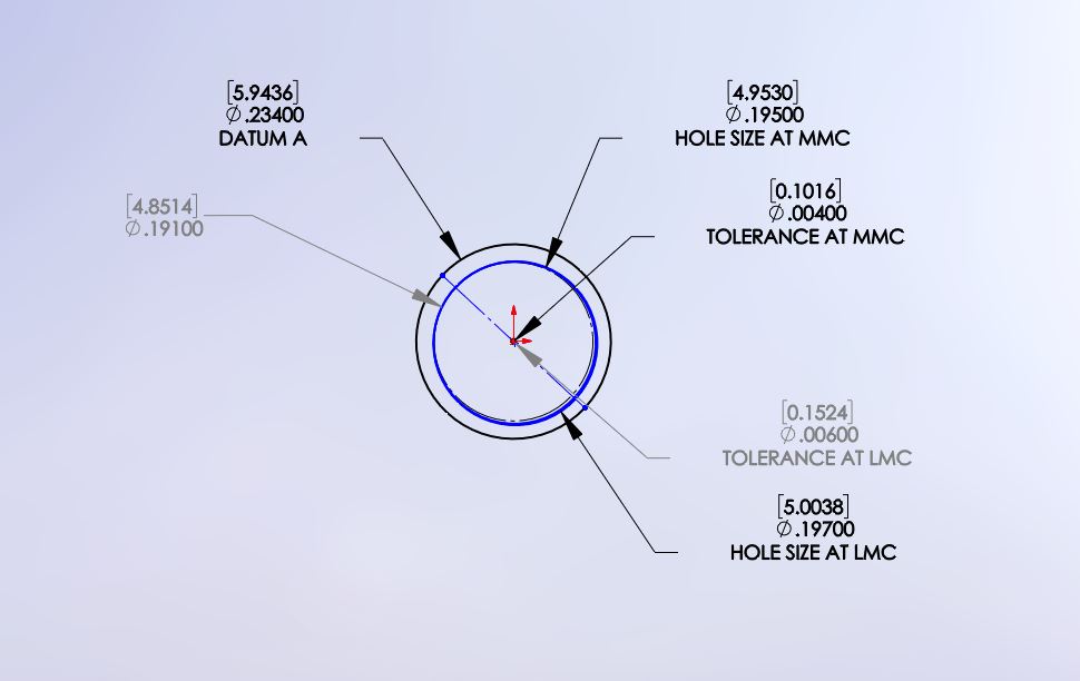
-
GD&T Runout @ MMC?
MattW replied to Matthew Hajicek - Singularity's topic in Machining, Tools, Cutting & Probing
You are in bad shape if you are relying on me for GD&T help. I think the datum A symbol needs to be attached to the extension line, not the dimension line, but I would have to check into that. You probably want a diameter symbol in your .004 tolerance block. You have your tolerance to A applied RFS. That may be what you want, I'm just pointing it out in case you want to (or can) apply the tolerance at datum A MMC. I like to draw out the limits of what I think the tolerance block allows in an attempt to see if I can make sense of it. -
GD&T Runout @ MMC?
MattW replied to Matthew Hajicek - Singularity's topic in Machining, Tools, Cutting & Probing
Since no one has jumped in yet- I've been told that position covers 80% of GD&T, so make sure you really need something else if you use something else. In this case, it sounds like position is what you want. According to this chart, runout is always applied RFS. GD&T Color Chart.pdf -
Hmm, can't seem to attach the files. I suppose I could send them to you if my description wasn't good enough.
-
This is the way I handle this. I don't know if the zipped files will come through. 1. Insert part into assembly, and save assembly. 2. Insert a 'virtual' part in the assembly to represent your stock. Model the stock. 3. Change the component display of the stock to wireframe. Now you can see your shaded part model inside the wireframe for the stock. Hope this helps.
-
If I am understanding your question correctly, several ways. What exactly are you after? Post up a sample file and I will take a look.
-
I have only run SW, so I can't compare. SW runs on the parasolid kernel, so parasolids should be rock solid. I have occasionally needed to import IGES, but it hasn't been anything too crazy. I have seen some demos and presentations on fixing imported geometry, and the SW tools look really slick. I have only really used them to fix issues with my own models.
-
Rather than extruding a pocket in SW, use the 'split line' command in SW. This will just put the edges of the letter on the surface you want to engrave, and then you can use that to drive your toolpath.
-
Vacuum hold down force is a function of the area you are sealing off to provide the force, as well as the vacuum level your pump can pull. Without knowing what you are using, I am going to guess you can pull 28"Hg fairly easily, which works out to around 14 psi. If the red box in your pic as the area you are sealing off, you are probably getting less than 50 pounds of hold down force. The amount of force resisting the part moving around is going to be a function of the friction between your workpiece and your fixture. Another thing to point out is it does not take much of a leak to spoil your vacuum. If your vacuum level goes up much when you pinch off the supply, you need a better seal/ tighter system. Also, don't cut through into the area you have sealed off. It may seem obvious, but... there is a reason I mention this. Looking at your parts, I would suggest a much bigger piece to start with. 10" x 10" would be very resistant to movement.
-
Thanks, Chris, I have Trevor looking at it (a resource I underutilize).
-
I have also been trying to tweak the Machine Definition to look like the one that comes in the MPMaster folder, in case that is the source of the problem. That hasn't helped, yet.
-
Post Revision 11.1.0811 I did a file compare with the MPMaster I dl'ed from the X5 link. There are some differences, but not ones that would obviously fix this. If I am to send the file to you through the site messenger, I am not smart enough to figure out how to attach files.
-
I made the changes you suggested, and it is still not behaving. Code snippets, 3 toolpaths. First two are on top plane, last is on front. G00 G17 G40 G80 G90 T1 M06 ( 1/4 FL EM CBD 3 FL MW090413) (MAX - Z1.2764) (MIN - Z.2763) M11 (UNLOCK) G00 G17 G90 G54 X-2.7267 Y-.9363 S6000 M03 M10 (LOCK) G43 H1 Z.6686 Z.4686 .... G00 Z.6686 (INDEX) <---- Feature, not rotational move X-2.9839 Y-1.0606 Z.4686 .... G00 Z.6686 G91 G28 Z0. (FLAT) M11 (UNLOCK) G00 G90 A-90. X-2.7547 Y.73 M10 (LOCK) G43 H1 Z1.27 Z1.07 ---------- I also found/was led to this part of the post, and uncommented the line as indicated. No change. pwrtt$ # Write tool table, scans entire file, null tools are negative if rotaxis$ > 0 | rotary_type$ > 0 | mill5$ <> 0, [ sav_rot_on_x = rot_on_x output_z = no$ ] if vmc = 0 & tlplnno$ <> 2, sav_rot_on_x = rot_on_x if vmc = 1 & tlplnno$ > 1, sav_rot_on_x = rot_on_x sav_rot_on_x = rot_on_x #Uncomment this line to output rotary axis value even when it's not used ------ I really like the idea of scanning the toolpaths and not outputting A if there are no rotational moves, but outputting them at toolchanges when there are rotational moves in the program. TIA
-
I need some hand holding here... Haas MiniMill with HRT160 4th axis, and I need A axis output at toolchanges, I am using a modified MPMaster post. Currently, I get no A output at the start, if A=0, and I do not get A output at a toolchange if A doesn't change. I have fiddled with 'sav_rot_on_x' and 'frc_cinit', to no avail. I get the unlock and lock codes, but no A. Currently, my G54 A0 is different from Machine A0. Any help appreciated. Code Sample: G00 G17 G40 G80 G90 T1 M06 ( 1/4 FL EM CBD 3 FL MW090413) (MAX - Z.6686) (MIN - Z.355) M11 (UNLOCK) G00 G17 G90 G54 X-2.7267 Y-.9363 S6000 M03 <---- Need A0 here M10 (LOCK) G43 H1 Z.6686 Z.4686
-
Keith got it right. The point being, ellipses and parabolas are similar but distinct curves. If you really really need a parabola, breaking up an ellipse won't do it. The irony of the misspelling is not lost on me.
-
At the risk of being pendantic, ellipses and parabolas are different kinds of conic sections with different equations. I would guess a spline through points would be your best approach.
-
And then makes some changes to the geometry. To me, this is where SW really shines, in that geometry changes are quick and easy, and, depending on how the model is built, a couple of changes automatically propagate to dependent geometry. Disclosure- when I was initially learning MC, my SW skills were so much better that I soon created everything I could in SW and just added the wireframe I needed in MC. A skilled MC operator is likely much better at geo creation and editing than I am, but I still guess that he would be fighting with one arm tied behind his back.
-
I am running 3DxWare version 10.0.10. I have traced it to the way I am implementing MC commands, which is to record a macro that performs the keystrokes. I have discovered if I hit ESC after the SP button, I get the regular behavior. So, I need to add the ESC keystroke to the macro and I should be good. But, there doesn't seem to be a way to edit the macro, only delete it and rerecord it. This makes me think the Macro approach isn't the right way to do this. I am considering going back to the latest released version of 3DxWare, which is kind of a shame because version 10 looks to have some really cool features. Documentation is really lean at this point, though. - - I just took a look, and the Macros are application specific, I think, so Macros recorded for MC aren't visible in other applications. So maybe macros are the way to implement the commands
-
I have the regular Pilot. I am thinking this is behaving like a setting in Mastercam, but it could very well be related to the driver. It seems to be working OK in Solidworks and G-Earth, the other applications where I use it a lot.
-
More wierdness. From the help file: Note: If you undock AutoCursor when you are not using a function that requires it, AutoCursor will disappear. It will reappear each time you initiate a function that requires interaction. For example, creating geometry using Sketcher functions. So I undock the Autocursor, hit the rotation center button, and the Autocursor toolbar pops up as promised, but still nothing is selectable. When I click on the top of the autocursor toolbar, then I can now select geometry. I have a bunch of autocursor options enabled, as well as 'Default to Fast Point mode' and 'Enable power keys'. I don't see a place to turn autocursor on or off, enabling settings turns autocursor on, correct? An auto rotation center feature would be nice, but being able to quickly select a rotation center is something I can live with. I would just like to get it working the way it was before.
-
Hi all I just got a computer upgrade to Win7, and finally got around to installing X5 as well. Aaand, I installed the new 3Dxware driver, yes, it is still in beta. I have a button mapped to set the rotation center, but when I go to do that, nothing is selectable. Until I go hit the All... button in the General Selection toolbar, and then behavior goes back to what it was before, i.e., I can select points on solids, arc centers, etc. Fast Point is enabled. Any suggestions on how to fix this? It sure would be slick if there was an 'auto rotation center' option like there is in SolidWorks. If it is already there and I don't know how to enable it, please tell me!

