Greg Williams
-
Posts
2,221 -
Joined
-
Last visited
-
Days Won
3
3 Followers


Recent Profile Visitors
5,818 profile views


Greg Williams's Achievements
")


-
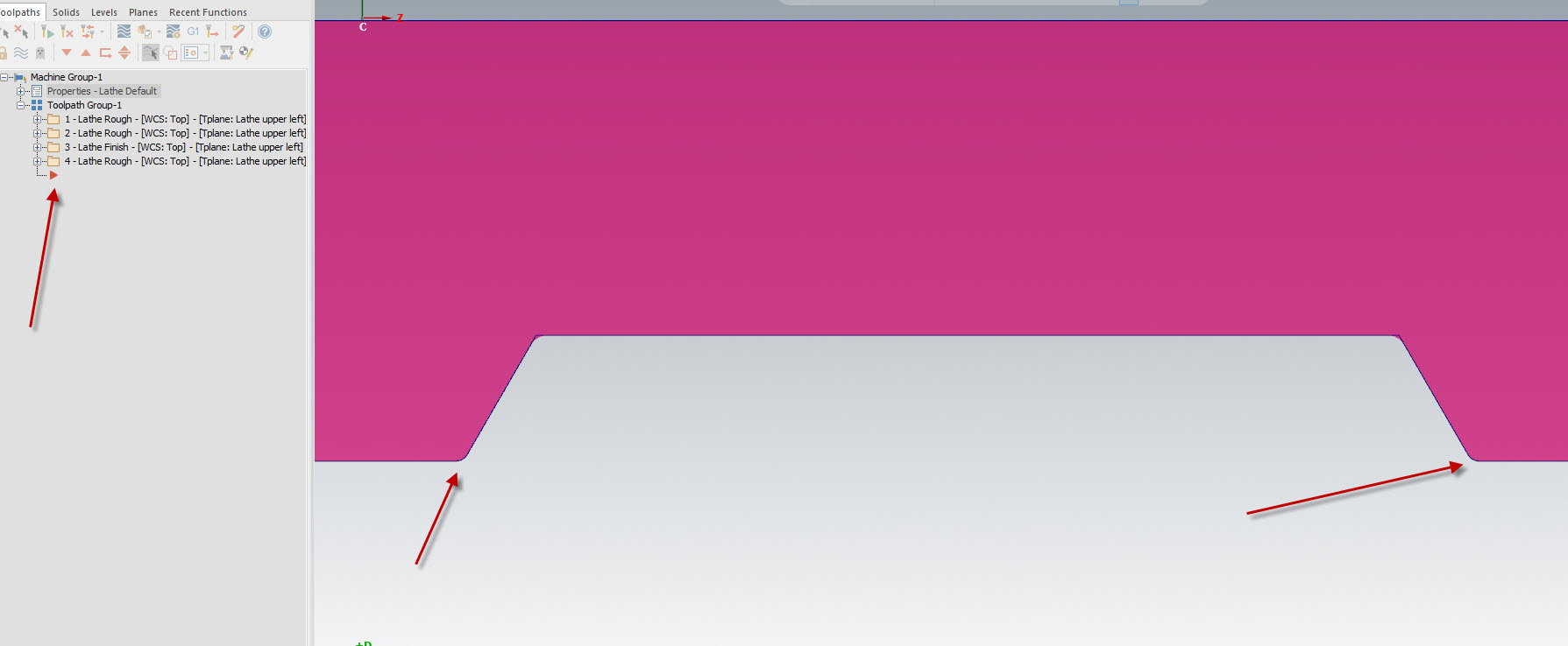
I dont think it can create reverse angles like that, you may have to draw it old school
-
Lathe toolpath not symmetric with reversed chain
Greg Williams replied to Azoth's topic in Industrial Forum
The file looks okay here, where is your operation arrow?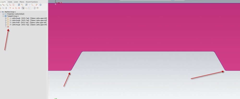
-
I have played with a few of these, are you using the DMG structure or running the MPF file?
-
Fanuc 5 Axis Parameters
Greg Williams replied to Cage86's topic in Machining, Tools, Cutting & Probing
Thanks for posting James, very useful info -
n_tpln_mch - what is its possible values?
Greg Williams replied to Giang-TT's topic in Post Processor Development Forum
If the G68.2 block spins the C axis table to a different place to what the Gcode is expecting the program will not cut the part correctly. Try my sample part of a machine and you will see the problem. -
n_tpln_mch - what is its possible values?
Greg Williams replied to Giang-TT's topic in Post Processor Development Forum
- With my simple approach, I used the toolplane vectors to get the i,J,K value directly. With this method, my tilted plane's X&Y may not align with the machine X,Y axis after applying the G68.2 (e.g. X100. command will cause both X and Y axis to move) ------------------------------------------------------------------------------------------------------------- Yes this is the problem with using the plane, we need to use the operations X axis - With your method, the tool plane's X&Y axis will be rotated to align with the machine XY axis after applying G68.2 . Am I correct? ----------------------------------------------------------------------------------------------------------------- Yes correct Your code is correct to calculate the Euler angle from the plane, but using the plane is not the answer. -
n_tpln_mch - what is its possible values?
Greg Williams replied to Giang-TT's topic in Post Processor Development Forum
YOu will need to add the code to transition from 3+2 to 5 axis and back again. You can cycle it back through p_goto_strt_ntl or create a new block -
n_tpln_mch - what is its possible values?
Greg Williams replied to Giang-TT's topic in Post Processor Development Forum
Hi Giang, If you use s_out and p_out to calculate G68.2 you will always get the correct result. if you use the plane you will not always get the correct result. If you use mi10 to flip the solution you will not get the correct result unless you flip the plane as well. Post ops 10 and 11, they should give you exactly the same gcode. T19 M6 G0 G54 G90 A-23. C180. G68.2 X0. Y0. Z0. I180. J-23. K0. G53.1 M38 M10 X0. Y-51.7542 S1800 M3 Op 12 is the same but the solution has been flipped with mi10, so hence the Y axis values are now inverted. G0 G54 G90 A23. C0. G68.2 X0. Y0. Z0. I0. J23. K0. G53.1 M38 M10 X0. Y51.7542 S1800 M3 Euler Angles.mcam -
n_tpln_mch - what is its possible values?
Greg Williams replied to Giang-TT's topic in Post Processor Development Forum
Giang, If you use m1$ to m9$ the plane will need to have the correct orientation, if the plane is not correct to the final machine orientation then the code will be different to what the G68.2 block is outputting. Post ops 8 and 9 of the attached file, you will see if your calculation is correct, both ops should give the same G68.2 IJK angles. G68.2 X0. Y0. Z0. I180. J-23. K0. If your machine is XYZAC you already have the 2 correct angles, if you have XYZBC or XYZAB then you will need to run the calculation or create a matrix and rotate the 2 angles you have back to AC orientation. Euler Angles.mcam -
Your Content file is empty.
-
Uploading a sample file will be best
-
n_tpln_mch - what is its possible values?
Greg Williams replied to Giang-TT's topic in Post Processor Development Forum
Giang, This can be done, For the G68.2 block I would use 2 angles not 3. If you want to use 3 angles you will need to create the Euler maths in a post block. If you create the maths use the new recalculated X axis vector from inside the post. If you use the toolplane to calculate the 3 angles the X axis may come out incorrect depending on how the tool plane has been created. Also you will need to write a block to handle the transition from 3+2 world to 5 with TCP on and 5 with TCP on back to 3+2 world with the same tool, currently there is no solution for that in the generic 5 axis post for this senario. Top Map will only output 1 or 2 off G68 blocks which will rotate the Gcode but on most machines I have seen the G68 will not datum track the rotations. For this we need G68.2 I have not used n_tpln_mch for any calcs but further down the string is mentioned and commented n_tpln_mch : -2 #Nutating machine selection when toolplane output I dont know who originally wrote the Generic 5 axis post but full respect to them as it is quite a document. -
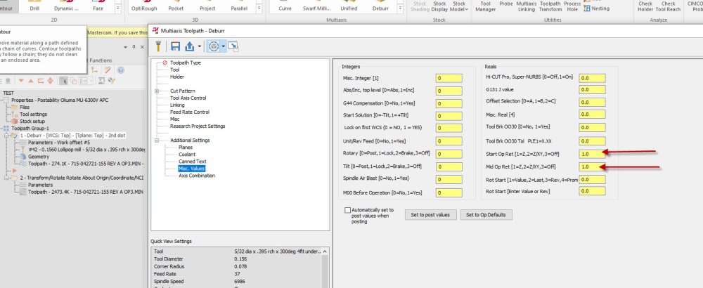
You could just change the Misc reals to 1 here. The code looks okay then
-
I get the same error, the code should be something like this at the transform. You will need ot contact postability through your dealer X2.33101 Y-8.36638 Z-4.6949 X2.3322 Y-8.36249 Z-4.68972 X2.3325 Y-8.35994 Z-4.68376 A-15.8438 G00 X2.33094 Y-8.34638 Z-4.63566 X2.27008 Y-7.81749 Z-2.75974 Z9. (2ND SLOT) X1.75446 Y-7.70568 Z9. A0. C0. Z-3.36978 Z-5.31978 G01 Z-5.36978 F10. X1.75506 Y-7.70555 Z-5.37745 F37. X1.75678 Y-7.70518 Z-5.385 X1.75945 Y-7.7046 Z-5.39237
-
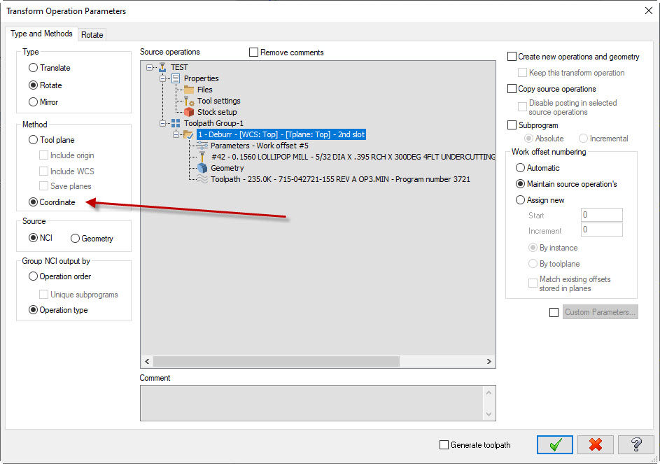
To transform 5 axis ops you should use coordinate not toolplane