ikertx0
-
Posts
97 -
Joined
-
Last visited
Content Type
Profiles
Forums
Downloads
Store
eMastercam Wiki
Blogs
Gallery
Events
Everything posted by ikertx0
-
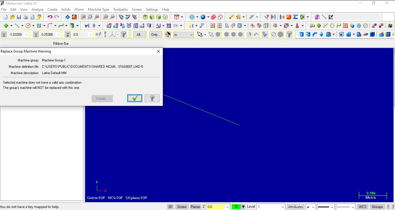
Hello! I am trying to recover an old post processor that I made for a lathe with Fagor800 control, from the X5 version, but when I update it I realize that it says invalid axis combination. I have opened it in X5, and it says the exact same thing. Anybody knows what could be the problem? Attached file in version X5, X9 and 2017 FAG800T.LMD-5 FAG800T.lmd-9 FAG800T.mcam-lmd

-
You also have the depth in incremental. Where is the arc selected? Can you post a picture? I think the arc is down there and it only increments 2 from down there
-
Could you make me a video example? I do not understand very well
-
how can I do it?
-
I need it like this, but instead of wired, solid is possible?
-
Yes, I know that option, but it only does it as 2D and wired, I need it in 3D
-
Is 2024 working well or should we stick with 2023?
ikertx0 replied to amw's topic in Industrial Forum
I'm still holding out on version 2023. Normally I don't update until update 3 is released, or if one of my clients needs it -
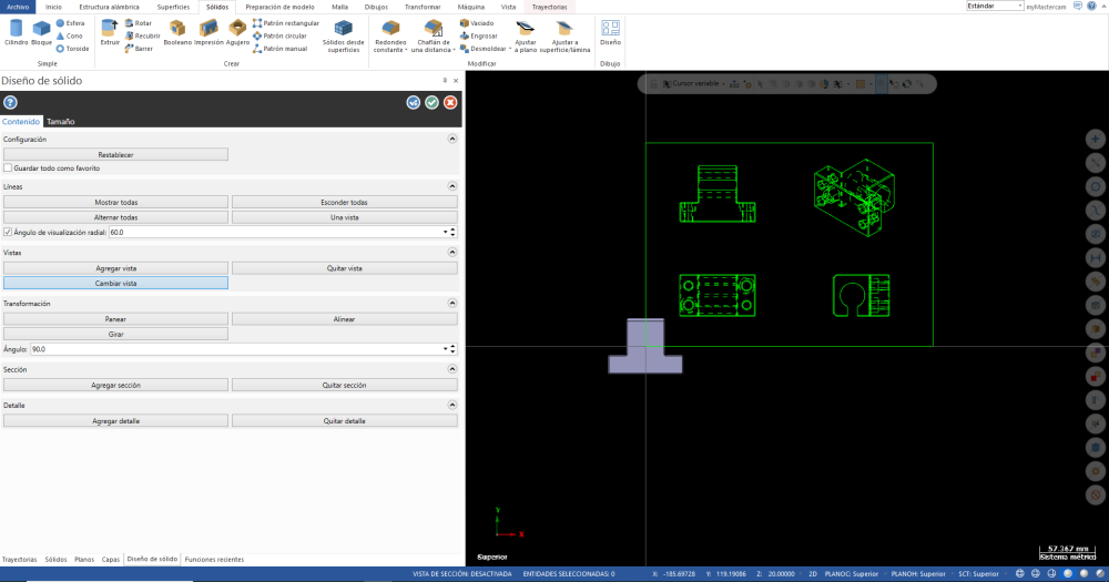
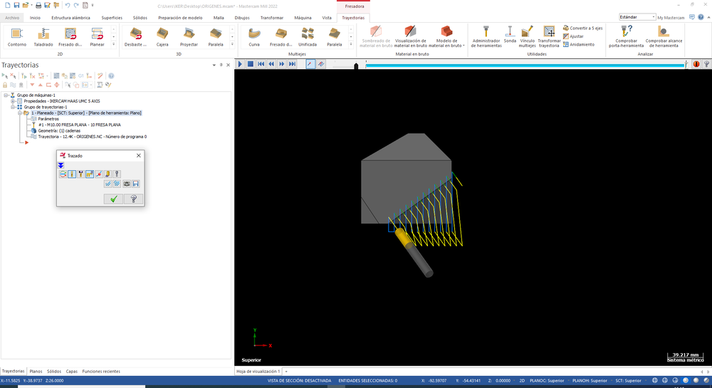
Hello friends! I have a question. Every time I do a program I need to print a sheet with 3 views + isometric, of the solid or geometry that I am machining. Is it possible to make a script with this information? Best regards
-
Incredible, have you done it? Do I have to place it in Mastercam plugin or other plugin?
-
Thank you very much, I didn't know that :D
-
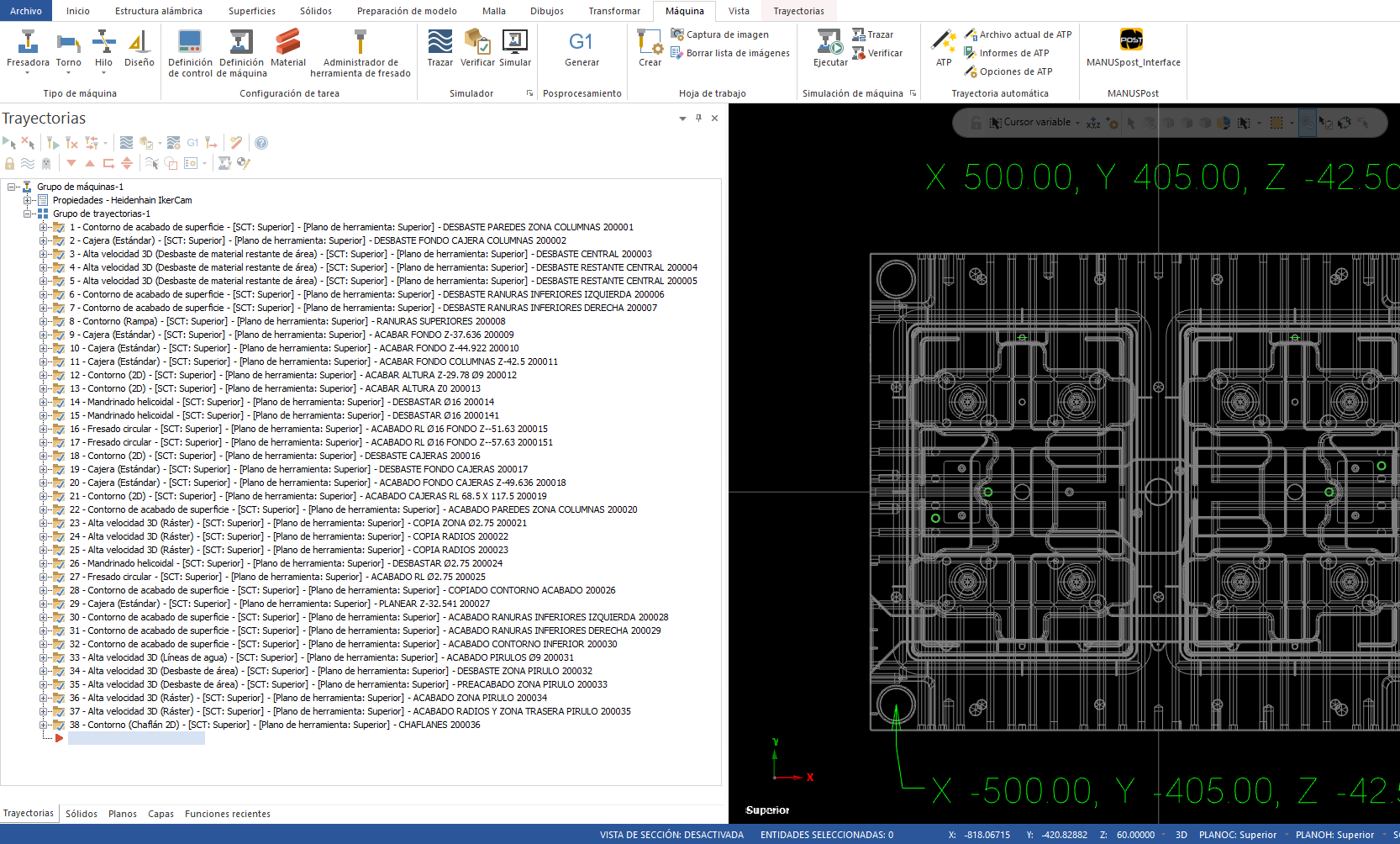
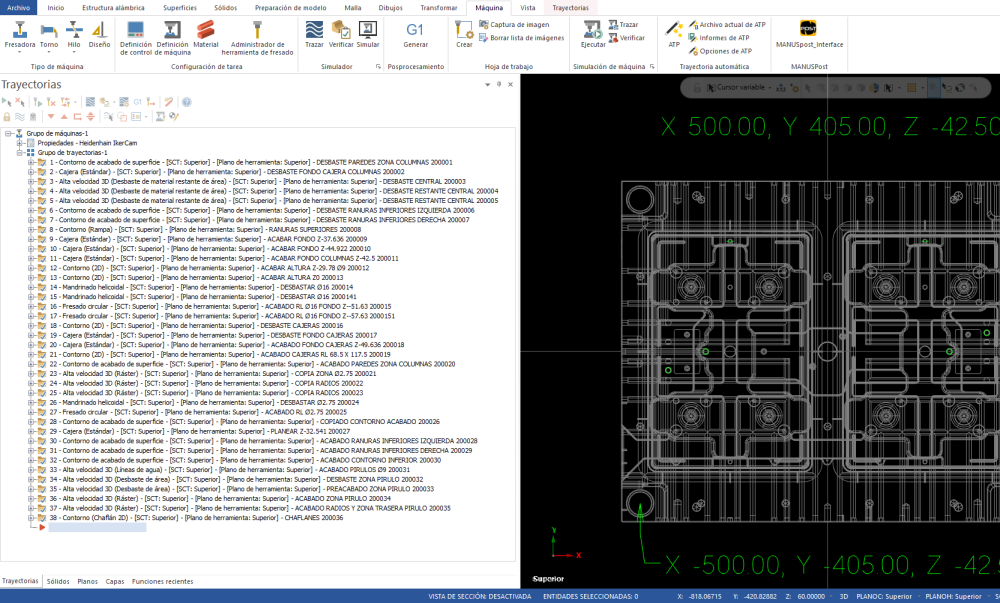
Good morning I have a client for whom I make programs and I need them as follows. Instead of one program with 38 operations, my client prefers 38 programs, each program with one operation. If, for example, the first program is number 200001, the last one would be 200038. Is there a script or a way to do it automatically, postprocess all at once, and generate each operation a program, with that sequence of numbers? Best regards
-
Hello, I am using this postblock, but the depth is calculated by infinity. The variable "count" it is not defined, since I have copied the code from the post above. force_dpts : 0 #Force XY output on all drilling lines including cycle call? #PARA PECK TAPPING fmt 4 peck_cnt #remaining no. of pecks #Peck TAP CYCLE fmt 4 numpeck # No. of pecks #Peck TAP CYCLE fmt 4 pass # pass counter use to calculate depths #Peck TAP CYCLE fmt "Z" 2 sub_depth #subsequent depths #Peck TAP CYCLE fmt "Z" 2 calc_depth # The total caculated cutting depth #Peck TAP CYCLE fmt "Z" 2 calc_peck # the calculated peck amount #Peck TAP CYCLE fmt "Z" 2 strt_depth # the first tap depth #Peck TAP CYCLE fmt "Z" 2 initial_calc # calculate the initial depth cut #Peck TAP CYCLE p_pecktap [ numpeck = peck2$ peck_cnt = numpeck initial_calc = (depth$ - tosz$) / peck_cnt strt_depth = (tosz$ + initial_calc) calc_depth = (depth$ - tosz$) calc_peck = calc_depth / numpeck "(PECK TAPPING CYCLE)", e$ pcan1, pbld, n$, *sgdrlref, *sg84, pdrlxy, *strt_depth, pcout, prdrlout, *feed, strcantext, e$ count = peck_cnt - 1 pass = 1 WHILE count > 1, [ sub_depth = strt_depth + (calc_peck * pass) pbld, n$, *sub_depth, e$ pass = pass + 1 count = count - 1 ] pbld, n$, sg98, pfzout, e$ pcom_movea ] pdrlxy #Drill XYZ coordinates if force_dpts, pfxout, pfyout, !zabs, !zinc else, pxout, pyout, !zabs, !zinc Some help?
-
incredible!!! thank you so much
-
Thanks With this information I have managed to make the turns work out well, but now I need to put the XY correctly, it is as if the X were changed by the Y and vice versa Correct rotations are Front A-90 C+0 Back A-90 C+180 Right A-90 C-90 Left A-90 C+90 Can someone guide me on how to change the X to the Y?
-
any helps?
-
I've made progress, but I can't get the turns and directions right #Preferred setup is pri. zero matches sec. zero/direction #Zero machine and determine the planes perp. to axis rotations #These plane combinations are valid: #Primary plane XY XZ YZ #Secondary or XZ XY XY #Secondary YZ YZ XZ #Primary axis angle description (in machine base terms) #With nutating (mtype 3-5) the nutating axis must be the XY plane rotaxis1$ = vecy #Zero rotdir1$ = vecx #Direction #Secondary axis angle description (in machine base terms) #With nutating (mtype 3-5) the nutating axis and this plane normal #are aligned to calculate the secondary angle rotaxis2$ = vecz #Zero rotdir2$ = -vecy #Direction #NOTE: Use of 'top_map' requires the dealer match the # above settings below. These must match initial settings!!! p_nut_restore #Postblock, restores original axis settings result = updgbl(rotaxis1$, "vecy") #Zero result = updgbl(rotdir1$, "vecx") #Direction result = updgbl(rotaxis2$, "vecz") #Zero result = updgbl(rotdir2$, "-vecy") #Direction 1.- L A+50.8636 C-35.5377 R0 F5000. L X+28.283 Y+31.713 R0 FMAX Must be A-50.8636 It’s OK L X+28.2826 Y+31.7128 FMAX 2.- L A-31.0027 C-123.6901 R0 F5000. L X-11.303 Y+76.801 R0 FMAX Must be C+56.3099 Must be L X+11.303 Y-76.8011 FMAX 3.- L A+90. C-135. R0 F5000. L X-56.567 Y-88.5 R0 FMAX Must be C+45 Must be L X+56.5665 Y+88.5 FMAX 4.- L A+90. C+150. R0 F5000. L X+58.299 Y+89.357 R0 FMAX Must be C-30 Must be L X-58.2993 Y-89.3569 FMAX 5.- L A-30. C+0. R0 F5000. L X+95.279 Y-50.979 R0 FMAX Must be A+30 It’s OK L X+95.2787 Y-50.9788 FMAX
-
Thanks Colin! This is the configuration of the machine Front A-90 C+0 Back A-90 C+180 or A+90 C+0 o? Left A-90 C+90 Right A-90 C-90 IMG_1647.MOV IMG_1648.MOV IMG_1650.MOV
-
I attach a test Mastercam file, and a TEST-OK postprocessed file that postprocessor generates the program well, and TEST-NOOK is the one I am programming, it rotates it. TEST-HEID-5AXIS.mcam TEST-NOOK.H TEST-OK.h
-
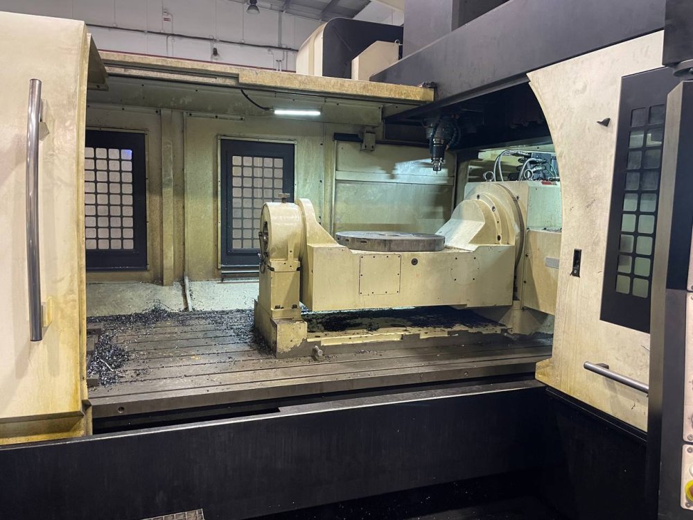
Good morning I am using a haas umc 500 and 750 psotprocessor to make one of heidenhain also 5 axes. I already have everything well programmed, but I have a mistake. In the Haas UMC machine, the B axis rotates about the Y axis and the C axis rotates about the Z axis. In Heidenhain, on the other hand, it has no B-axis, and the A-axis rotates about the X-axis. The C-axis is the same as in Haas. My problem is that the machinings come out rotated, as if they were machined along the Y axis, instead of the X axis. Is there any way to fix this? Best regards
-
Can this be implemented in the generic VF-TR?
-
Converting Post VF-TR to UMC 750
ikertx0 replied to ADV_Cole97's topic in Mastercam C-Hook, NET-Hook and VBScript Development
Is that value better to set to 0, or set to -40? -
up!!
-
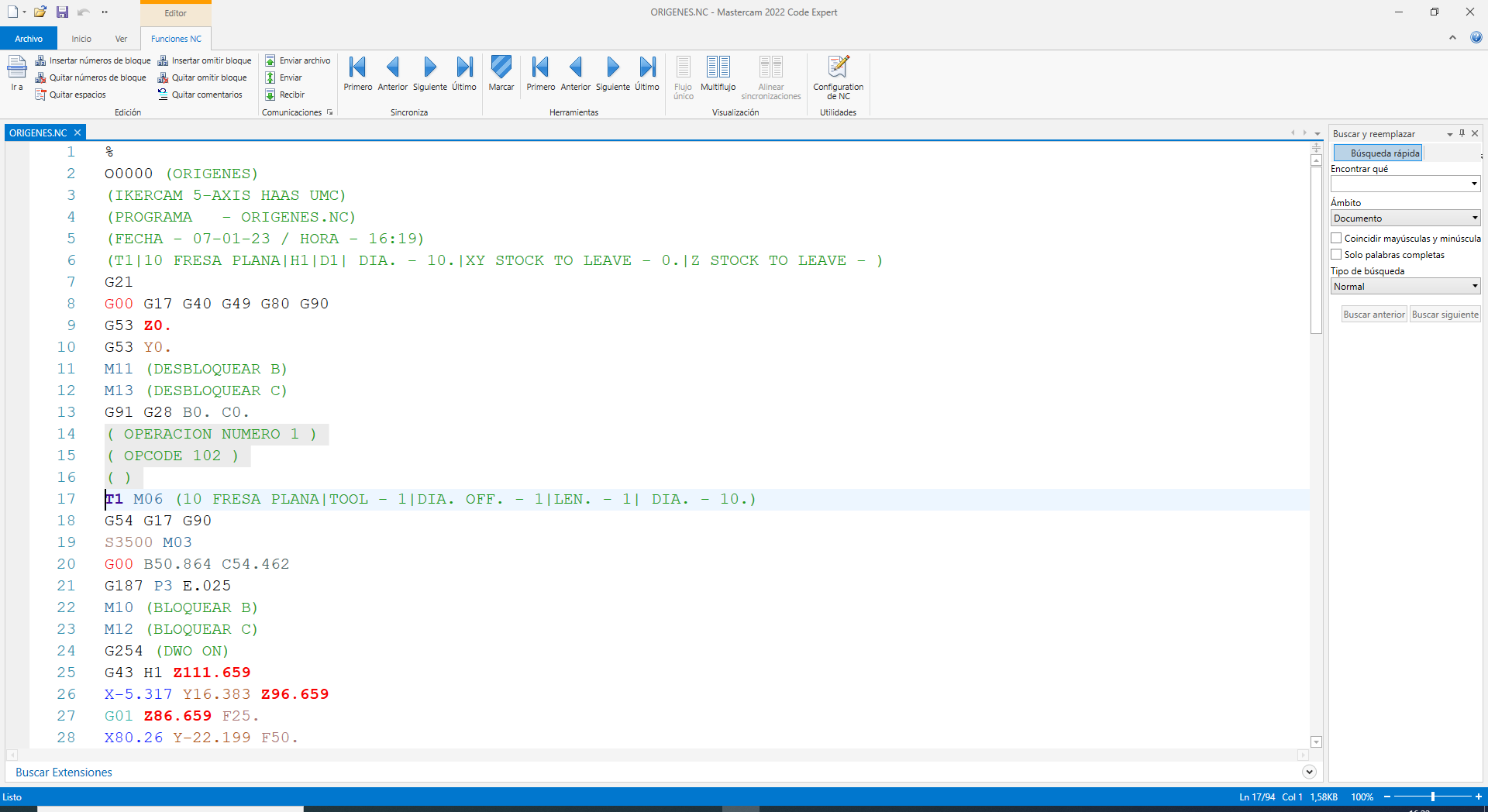
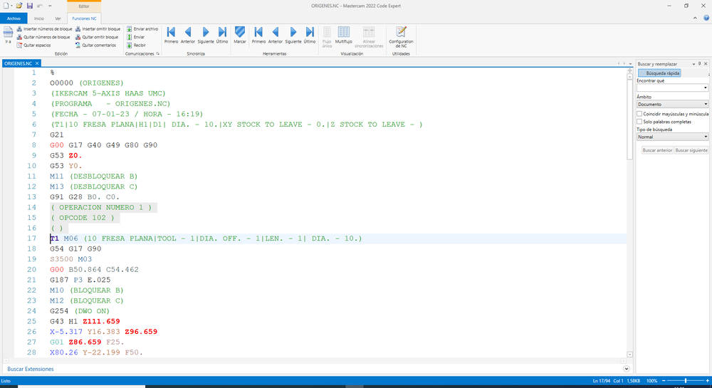
Hello Happy New Year! I have a question I want to add a post processor that shows the type of operation it is. For example I am doing a Facing, which according to the opcode$ / Tool_op$ list is number 19. so it should stay like this Planeado in english y facing sm_op_type : "" if opcode$ = 19, sm_op_type = "FACING" pbld, n$, scomm_str, *sm_op_type, scomm_end, e$ Up to here everything is fine. I have also added an opinfo table with the value 15238 to know exactly the number of op_code. It turns out that if I do a facing, it tells me that opcode = 102 But it never shows me the text in my post processor. Some help? fmt "OPERACION NUMERO " 4 sm_op_number fmt "OPCODE " 4 sm_opcode resultado : 0 sm_op_type : "" #tabla de valores fprmtbl 101 2 15240 sm_op_number #numero real de la operacion 15238 sm_opcode p_opcodes if opcode$ = 102, sm_op_type = "PLANEADO" if opcode$ = 19, sm_op_type = "PLANEADO" p_asignar_valores resultado = fprm (101,0) p_optipoop p_asignar_valores pbld, n$, scomm_str, *sm_op_number, scomm_end, e$ pbld, n$, scomm_str, *sm_opcode, scomm_end, e$ pbld, n$, scomm_str, *sm_op_type, scomm_end, e$
-
an example of the programming although I know that it is not correct, that's why I want to know the opinfo values of SPA SPB SPC fmt "SPA" 2 sm_SPA_x fmt "SPB" 2 sm_SPB_y fmt "SPC" 2 sm_SPC_z sm_SPA_x = s_out sm_SPB_y = d_out sm_SPC_z = p_out p_planespatial n$, "L", *s_out, *p_out, *sg40, *feed, e$ #just to see the turns n$, "PLANE SPATIAL", *sm_SPA_x, *sm_SPB_y, *sm_SPC_z,"TURN MBMAX FMAX SEQ- TABLE ROT", e$
-
Hi mates I am trying to program a postprocessor for heidenhain tnc 640 5 axis, starting from the generic fanux 5 axis base. Apart from programming, I am getting many values from mcam 2023 parameter ref. Now I am trying to program the spatial plane, I need the opinfo values of SPA SPB SPC, since nothing appears in the parameter ref book. Can someone tell me what those values are? Thank you very much Example: * - T10 = 35-R6 | DIAM. D+35. | RAD. ESQUINA R+6. TOOL CALL 10 Z S1650 CALL LBL "SAFE" M3 M140 MB MAX PLANE SPATIAL SPA+89.0048 SPB+0. SPC+0. TURN MBMAX FMAX SEQ- TABLE ROT L X-57.6125 Y-10.8322 FMAX