


tim_h
-
Posts
118 -
Joined
-
Last visited
-
Days Won
1
Content Type
Profiles
Forums
Downloads
Store
eMastercam Wiki
Blogs
Gallery
Events
Everything posted by tim_h
-
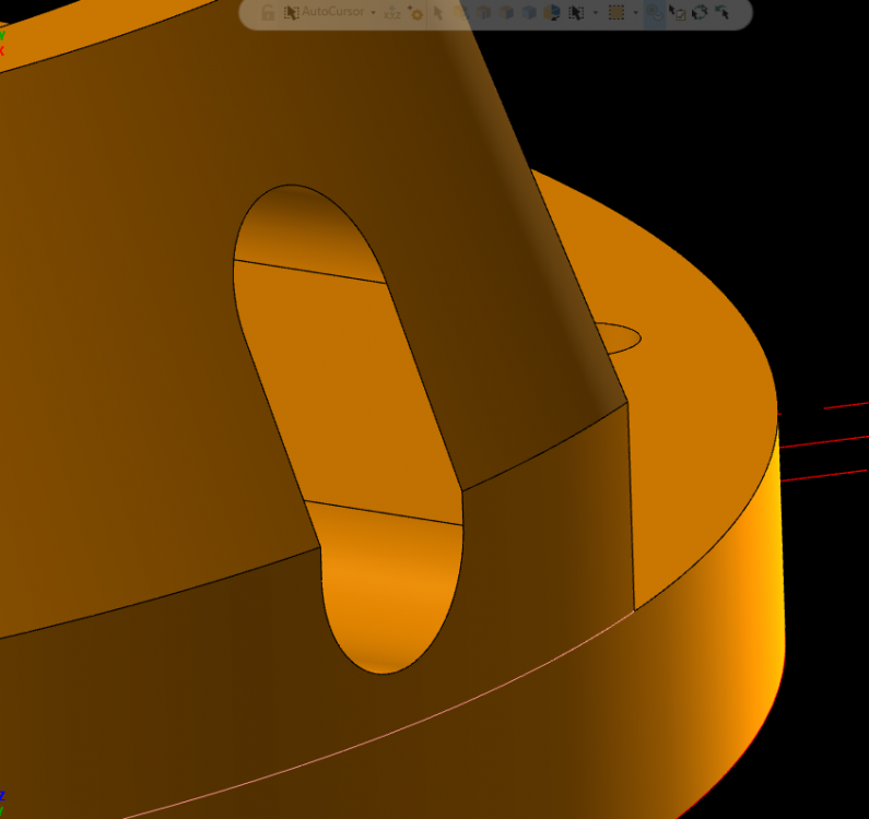
But not on the upper section. I'm thinking i'll just send it over without the chamfer, I guess they are doing a manual check on it anyway. Thanks !

-
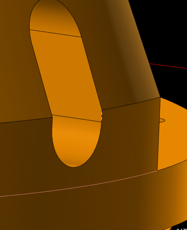
I was able to get the bottom part to chamfer in Solids if I select the small vertical piece.

-
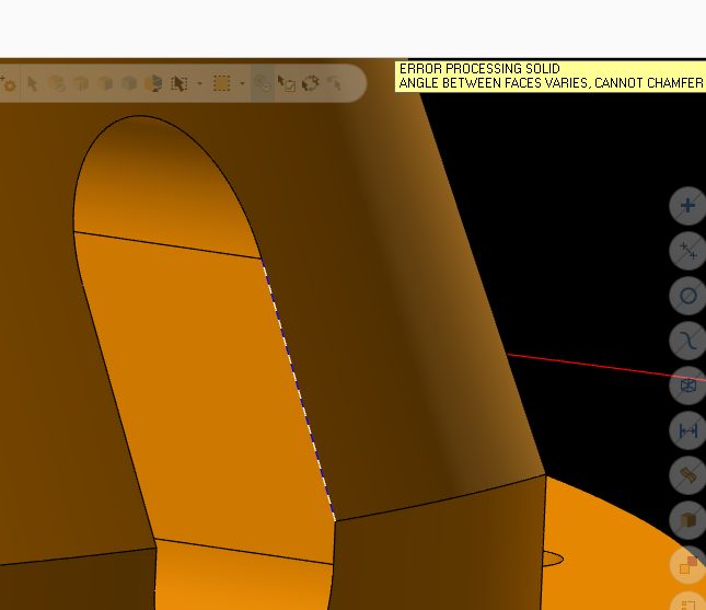
SOLID CHAMFER isn't working on this feature. I did try one piece on the angle and then again on the OD but no luck. I haven't tried a sweep cut... yet I was thinking if they really had to have it a BOOLEAN REMOVE with another solid as the cut tool may work. But a more lengthy process.
-
Is there a simple way to put a chamfer on (model) this oval ? I can cut it, but wanted to know if it's possible to model it. QC is going to want to see it on the model I give them.. THANKS
-
I wanted to try to create an STL from the stock model to use for when I flip the part over on op2. I know you can save a STL from your VERIFY result. I also use stock models for rest machining, and "current part shape".
-
2018 - LATHE - is crashing on me when trying to create/update a stock model. Like immediately crashing after I added some c-axis toolpaths. My part has c-axis holes and two slots on the face. It doesn't like when I added a "C-AXIS FACE CONTOUR" to mill the slots. It's probably me, but thought I would ask if anyone else has seen this ?? I'm a long time user of MC, current with X9 . I have been programming 3-4-5 axis mills (3+2 anyway) Lathe and 2018 are both new to me.... still trying to get a handle on the Lathe side.
-
Just re-affirming...
-
The example above works on our Matsuura MX-520.. I had some issues as well when the machine first arrived. A call to our machine seller is all it took.
-
https://docs.google.com/spreadsheets/d/1yhpORsw2T_xgUcLdK_eKOYGTmPnf-szBp_y50yzTocI/edit?hl=en&pref=2&pli=1#gid=1 this one ?
-
http://www.inhousesolutions.com/2015/11/importing-custom-tool-from-level/ How about this ?
-
Thanks for taking the time on this ! I very much appreciate the help and support I get from here
-
Under the Operations Manager r-click set DISPLAY OPTIONS, check the box next to WCS(name) and TOOLPLANE(name). Then it will show up next to your toolpath type in your operations tree. ex; Facing-[WCS:TOP] - [Tplane:Front] Contour(2D)-[WCS:TOP] - [Tplane:Front]
-
The 1st chain is the shape...the 2nd chain is the "cut this shape" along this chain This is almost verbatim what I say to myself while toolpathing SWEPT2D Re-ordered, check. Re-chained as well. Both ways. Also tried all possibilities on right and left settings. Someone was on my computer whilst I was running from IRMA for a few days. He may have changed something... He is on VAC now though.
-
Yeah I did that too. That's when I got that real ugly tool path. So I went and created new tool paths and changed the order of which I chained, both ways, and still no luck. DIRECTIONAL BUTTONS ?? Under CHAINING OPTIONS ?
-
yes, THAT is exactly what I was after. My 2017 BETA has expired so I can't open your file. Until this company re-ups their maintenance... I had to push pretty hard last time around When it works it's very short and simple. I'm not sure what my problem is here on X9. THANKS !
-
Thanks for trying ! I got a SWEPT 3D to work too, but it wasn't until after I had RASTER and WATERLINE tool pathed it.
-
Here is a stripped down version. It's not a solid anymore just sheet body. I made a curve slice on the sheet body then tried SWEPT 2D and got the same results. SWEPT 2D CHALLENGE.mcx-9
-
They are LINES and ARCs.
-
No skew... all lines are on the same y axis. They were created from a curve slice. All geo is squared up with axis'. Thanks for taking time for this ! I'll look more monday a.m Have a great weekend !
-
I then gave up and went with WATERLINE and RASTER to get it. BUT I SWEAR I HAVE GOT IT TO WORK IN THE PAST...
-
Thanks I did give 3d SWEPT a shot and it didn't look right. I thought perhaps I needed to offset the GEO and use the tool CENTER instead of TIP...
-
I have not used this toolpath for a while. I thought I could change the order in which I chain the WF GEO and get a nice path that would run up and down the angled wall (UGLY) . This is all I could get... I swear I have conquered this once before, but no such luck this time. Am I missing something ? I have tried .250 and .125 ball Endmills, same result. I wanted to step the .250 ball into the corner leaving a .125 radius. The tab is about .350 tall. Using X9 Thanks for looking !
-
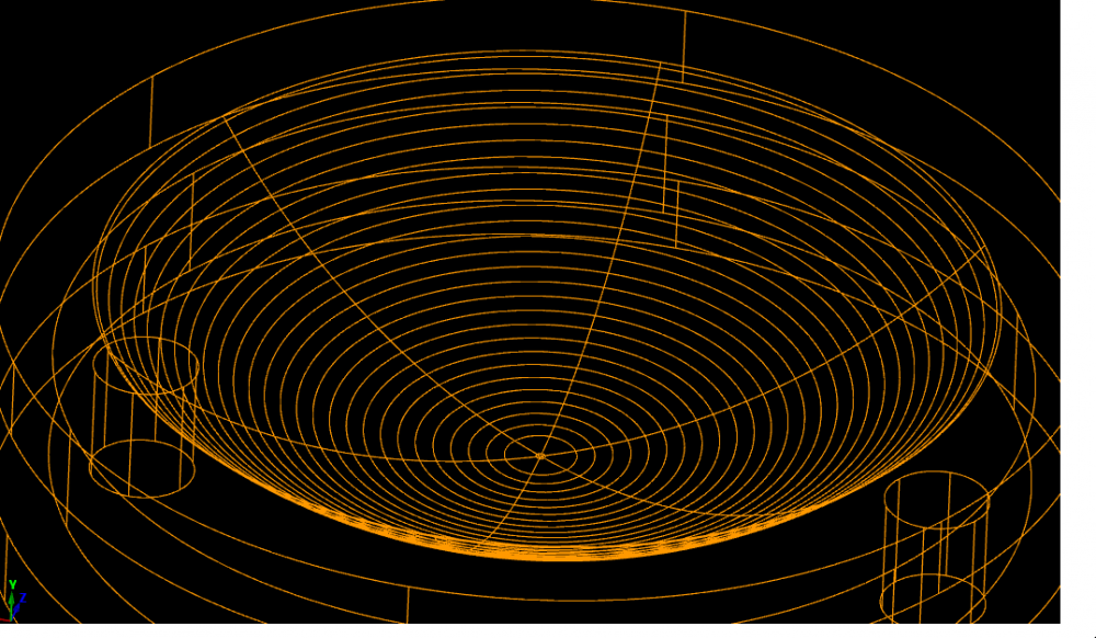
This. Arc segments... I created another ellipse using NURBS. There is the option of using line segments, but I thought that may not be what I am after. I tried to get the "NURBS" ellipse to revolve cut and and no luck. I hope these arc intersections don't show up in the part. It it less than an 1.0 in diameter. So i'll use as large a tool as I can.
-
GOT IT ! Simple , I just needed to use "trim 2 entity" on the cross and vertical lines to the Ellipse intersections... Although if you look close the surface look a bit faceted..


-
no But i do have that as my next step. I did a search and that came up on other threads.


