


LeoC
-
Posts
72 -
Joined
-
Last visited
Content Type
Profiles
Forums
Downloads
Store
eMastercam Wiki
Blogs
Gallery
Events
Everything posted by LeoC
-
eMastercam Multiaxis Essentials 2017 MC4SW rolldie question
LeoC posted a topic in Educational Forum
Hi: So I am working on the tutorials so that I can learn how to run our 4th axis on our Haas machine. I use MC4SW exclusively, my coworker uses the stand alone version. I opened the tutorial 3 file and converted it to a parasolid and opened that in MC4SW. This particular part requires a function called rolldie to complete the machining process. Well, MC4SW pretty much doesn't come with any C-hooks, so how do I finish machine this part? I can't find anything remotely similar to what is shown in the training manual. Any suggestions are welcome. Did I shoot myself in the foot by purchasing MC4SW? We bought MC4SW when it first came out so we do not have the option to use either or on our license, at least without me bumping off my coworker off of his seat. Thanks, Leo C TUTORIAL 3.mcam TUTORIAL 3 MC4SW.SLDPRT -
Simple. Thanks and have a great weekend LeoC
-
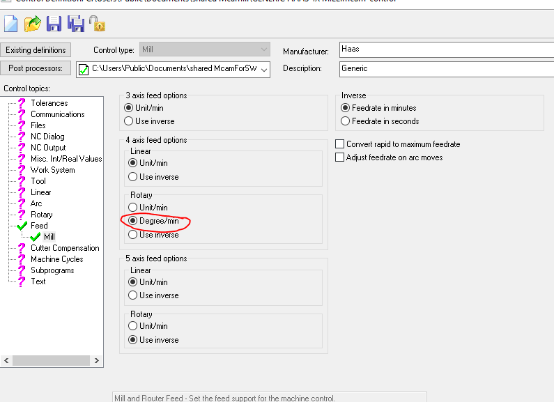
Looking at my control definition, I see this, see attached. I changed it under the 4th axis section to inverse and now it posts a G93. LeoC
-
Thanks Roger, I am using the same post and definition that you are. I noticed in your posted code that a G93 is not called out. Is that because when we set up the 4th inside the machine we enter the diameter of the part? Or does the posted code need to be edited to show a G93? Thanks for taking the time to answer my questions. I am usually the go to guy here in this shop for the micro machining stuff so the 4th is new to me. LeoC
-
My feed rate was only 15 IPM. Is inverse time the preferred method for 4th axis moves? Thanks for taking a look at that. LeoC
-
Hi: It has been about 15 years since I have programmed for a 4th axis and that was in Gibbs. This is being done on a Haas and programmed with MC4SW 2019 and I used the generic 4th axis post. The stock is 2.5" in diameter and programmed from the centerline using a 3/16 ball end mill. The thing that I am concerned about since I am inexperienced with 4th axis programming is that the feed rates seem pretty high. Can you please point me in the right direction? Thanks. LeoC sample engraving.NC sample 4th engraving.SLDPRT
-
I think this might have something to do with your having used the Beta program. if I remember correctly, you needed to uninstall the Beta package and also clear the registry of all of the Mastercam installs and then load the new version which is on the download page from CNC Software. Then it will install the "clean" version and then it will recognize that it requires updates. I believe there have been three updates so far. LeoC
-
I have the Renishaw probe package on the Haas that I use although I am not an expert. Are you trying to use a custom cycle? That cycle does not look familiar to me. The software for the probe is located on the memory stick in the back of the cabinet if you wanted to reload the original probe software. LeoC
-
Have you tried going here for more info: https://diy.haascnc.com/how-productivity-and-programming-solutions?v=001#gsc.tab=0 . LeoC
-
How do I get to tool path editor with MC4SW? LeoC
-
Or mount your 4th axis so the rotary axis is pointing in the z axis, then rotate the part and move the table x any. The poor man's way of doing it. LeoC
-
I remember that stuff from my bicycle building days. In order to fit the tubes together, we had to use a grinding wheel whereas with anything else, even Ti3Al/2.5V, you could use a hole saw. Nasty stuff to work with. Other people were able to make frames with it but we felt it wasn't worth the effort. LeoC
-
I am curious to know how you set the tool height with such a small drill. I have been looking at a Parlec optical tool pre setter but even using that, they recommended something like minimum size of .005". LeoC
-
These guys might have what you need: https://us.mikrontool.com/en/Products
-
picking up tooling ball with Haas Renishaw probe
LeoC replied to LeoC's topic in Machining, Tools, Cutting & Probing
Thanks guys! It looks like I was on the right track. LeoC -
So we have a new part that we are working on and it will require picking up the center of a tooling ball to indicate the center of the part for X and Y location and also establish the vertical location for centerline of the tools. I am assuming I can do this by using the standard measuring cycles for probing a boss and then use the Z surface probing routine once the probe is positioned X and Y over the part. Is this feasible or is there a better way? I have never done anything like this. thanks, LeoC
-
help with tight tolerance cylindrical part
LeoC replied to LeoC's topic in Machining, Tools, Cutting & Probing
Unfortunately, this part does need to hold those tolerances in order to do what it needs to do. LeoC http://novoengineering.com/ -
help with tight tolerance cylindrical part
LeoC replied to LeoC's topic in Machining, Tools, Cutting & Probing
I agree, it really should be classified in the "class fit" format as all we are interested in is the clearance between the two pieces, not to an exact size. I know it is easy to make fun of the engineers but in this case, this has to be this tight to perform a certain function. This was designed by some Doctor's so yes, it can be challenging at times. So far we are going to try turning the part as close as possible and then send it to an ID grinder that says they can do it, we'll see. I'll let you know how it turns out. LeoC Here is a link to where I work so you can get a better idea of the stuff we do here. The photos of the machine shop area are quite old and need to be updated. http://novoengineering.com/ -
help with tight tolerance cylindrical part
LeoC replied to LeoC's topic in Machining, Tools, Cutting & Probing
Thanks for the responses so far. As I mentioned earlier, we are a product design house and we have a machine shop in house. I work in the machine shop with two other guys. So we make all kinds of things, scientific instruments, medical equipment, consumer devices, just about anything, always something different so can be interesting at times. This part has a mating piece that goes inside. Talking to the engineer more, the main concern we have is the clearance between the two parts so they can be match fitted per se. So if the ID goes too big or small, the mating part can be changed just so long as the clearance between the two is what we require. We appreciate the feed back and knowledge of the members of this forum. LeoC -
I work in a product design house and we have 50 engineers always challenging us with some tough jobs. This part is a little out of our expertise here in our machine shop and we were looking for some advice to see if this part is doable and suggestions to make it easier. If you happen to be interesting in making the part, there is a contact on the pdf or you can PM me here. Thanks for the help, LeoC outer-cyl.PDF
-
Thanks for the replies. I see that Vardex has exactly what I had envisioned. Now to get approval on this project. LeoC
-
I use MC4SW and when I have that happen, it is because one of the ops has a different name. Sometimes that happens when you copy an operation from another program into your part. Right click each tool path and check and make sure the names are all the same and then try posting again. LeoC
-
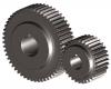
Is it possible to cut gears like in the pic attached on a Haas cnc mill with a 4th axis? And if so, where would I buy the cutters? LeoC
-
Thanks for the replies guys. We'll talk to the management and see what solution we can come up with. LeoC
-
Anyone with experience with running a swamp cooler in a machine shop? Does it cause any rusting issues? It isn't practical in our machine shop with the 20 foot roof height to drop a ceiling so currently we just use industrial fans to blow the hot air around. We have the portable AC units at our desks but then when we walk and work around our machines, it can get pretty hot. Just looking at different options. LeoC

