


mirek1017
-
Posts
888 -
Joined
-
Last visited
Content Type
Profiles
Forums
Downloads
Store
eMastercam Wiki
Blogs
Gallery
Events
Posts posted by mirek1017
-
-
11 hours ago, Jese said:
I have a haas st30y and am trying to put a radial pocket on the side of the part as pictured. It looks good on mastercam but wants to gouge into the part on the machine. I need to use the y axis to put the feature in. I tried c axis contour with y axis also tried mill countour with y axis output. Both want to gouge into the part. Any ideas of what’s going on here?


In lathe settings you have option for axis combination Y and C ,you need to marck C
-
3 minutes ago, Jake L said:
I believe the only generic post that supports right angle head is MPROUTER.pst.
So your options are:
1. use MPROUTER and hand edit the gcode for all your M-codes. This will get you correct x/y/z moves.
2. modify MPROUTER to output good code for your machine
3. buy a post for your machine that supports right angle head
I am get to ikea post from mastercam,web the haas and fonuc and still posting wrong
-
28 minutes ago, mirek1017 said:
Thank you ,let me take look
SOo I am set up my angle head in my mashie deff
when I oposting code looks like is something wrong ,the ,how I can change Y to Z?
-
4 minutes ago, Jake L said:
Honestly if it's a simple cut the easiest way to program it is point to point.
To get Mastercam to output code for a right angle head you need to modify a post, modify a machine def, and there's no way to actually simulate the tool for verification in Mastercam. Here are a couple links for you. The youtube video is long and old, but it is what I followed to get right angle head code output from MC.
https://www.youtube.com/watch?v=lxhlx5wa97o
Thank you ,let me take look
-
Hello ,someone programing it ?
Just now, mirek1017 said:Hello ,someone programing it ?
I need to cut keway on big cam
-
9 minutes ago, CEMENTHEAD said:
Some of our machines will not pull a program with an "O" have to rename it with a ":" (colin).
Thank you for reply
I think we find out this one
-
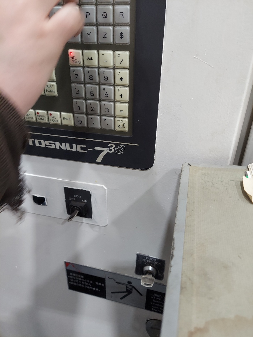
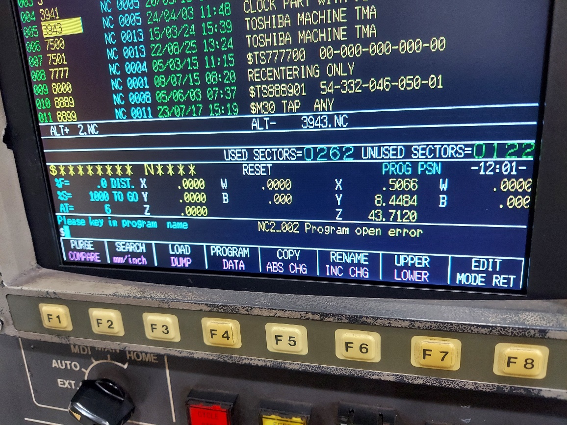
Hello
We try set up a aure HMC with tosnuc 732 control, when I load the program I start running, the alarm show up
Anybody can help what is the problem ?


-
40 minutes ago, AHarrison1 said:
My settings are the same as what you have shown.
Are use 2024 ?
-
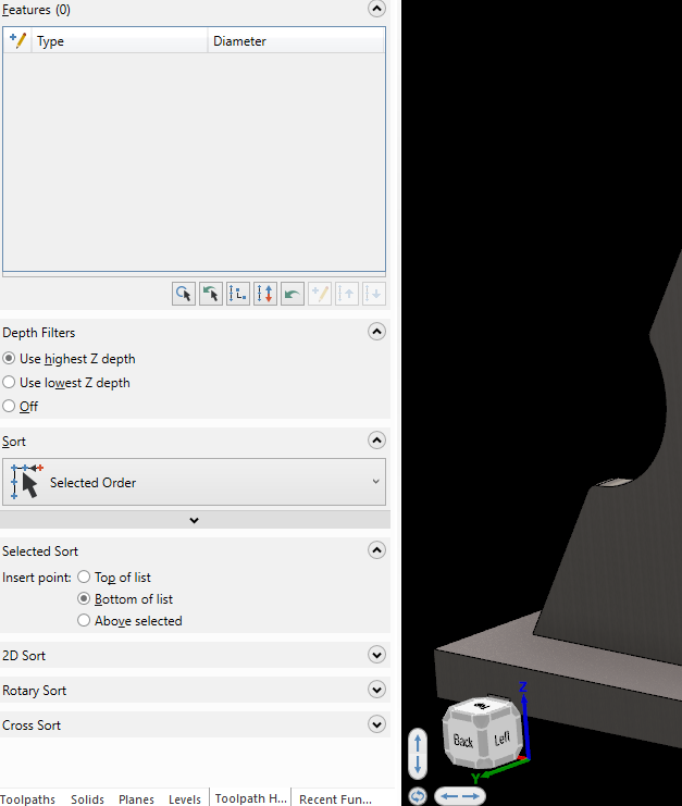
1 minute ago, AHarrison1 said:
For me it picks the holes in the same direction
What about this setting
-
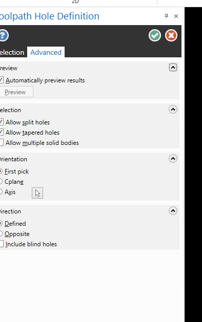
6 minutes ago, AHarrison1 said:
I think Ctrl+Shift+click for holes on the same vector will be your solution.
tank you for your reply ,when I use this option pick up all holes like on the picture
-
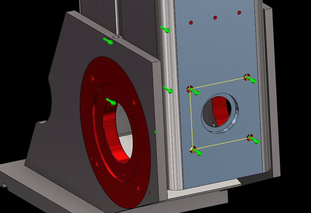
Hello All ,how I can pick up holes only on my blue face ,when I use ctrl shift mastercam pick up all the same holes on on my front face what I am working and on the back face .
thanks for any helps
-
15 minutes ago, bird2010 said:
Sorry, my English is not good. I don’t understand what you mean?
Your stock is wrong, I did not use it, because 2 times using 3D high-speed Contour does not require the use of stock! Just control the depth...the focus is on the use of the tool
Use END MILL or END MILL BULL (very small R)....
I only created another stock to simulate using it. I think the simulation results are acceptable...I can use the 3d toolpath for finish from the small holes side ,but the will be very hard use sime enmill for other side ,I need over 6 inch long enmill
I am still didnt see this
-
13 minutes ago, mirek1017 said:
I an use the same thing and still do not work for me

ok ,I think I see some flats on my stock is beacos I am make to deep 3 inch hole on my lathe on face
thats why I have problem for blend it all together
46 minutes ago, bird2010 said:...

can you run your toolpath on my stock for blend oper ?
-
27 minutes ago, bird2010 said:
...
I an use the same thing and still do not work for me
-
2 hours ago, bird2010 said:
Using 3D high-speed Contour
Use END MILL or END MILL BULL (very small R)
Maybe there is a better way...
what toolpath are using here ?
-
2 minutes ago, crazy^millman said:
Need to find out fi a radius is allowed. If it is then use a ball endmill that radius to blend that section. Want a sharp corner then I would consider Sinker EDM. On a 5 with a taper ball endmill can get close, but sharp corner milling yes not really a way on a HMC on my quick review I could see.
But when I try to use 3d contour toopath for finish this I can see the will be still som flat section on the part
-
2 hours ago, crazy^millman said:
The sharp corner concerning you? Looks like good toolpaths to me. What is your specific question to know how to help? Sorry that is to vague a question.
I don't know how I can explain this to you
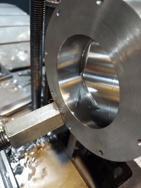
I have this mdel from the costumer .So my plan was to set up this for lathe ,turn od and make face bore 1st .So after that I am creating working plan from the center line of side bore and I am use helix toolpath for rough .When I am make veryfy I see the I I can't go all to the bottom becose I will hits in the wall of the face bore ,
So ,I am create other operation and working plane and try use some rough 3d toopkath and 3 finish ,but I don't know haw I can finish this with rhe same results what solid
For me this is not doable
-
1 minute ago, crazy^millman said:
For a $1,000,000 I am wiling to give it a shot.

I thought so
-
-
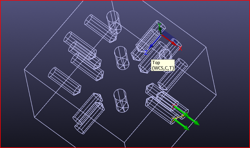
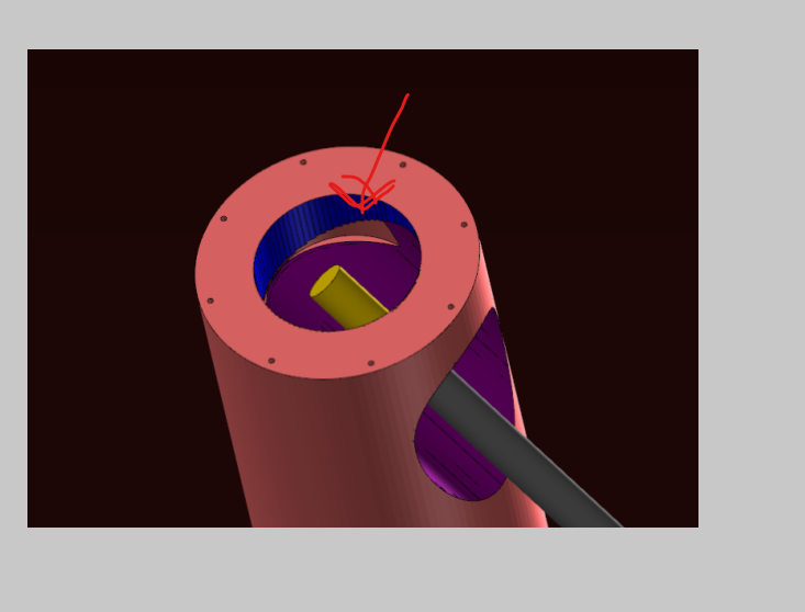
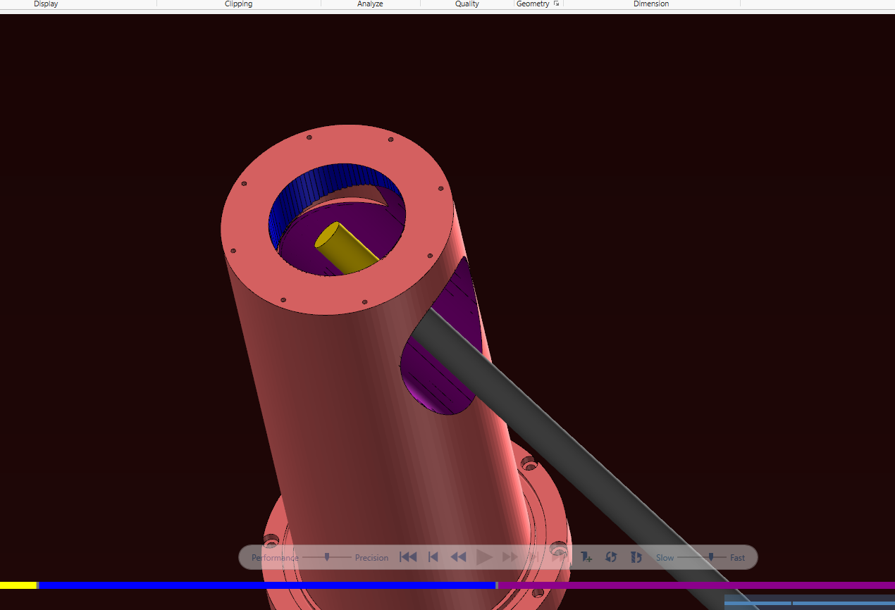
Can some one can help me on this sample , I am open old program ,the other program marck one hole and rotate toolpath around x
I am try ise 5 axis drilling marck all holes but do not work ,

4 TH AXIS DRILLING.MCAM-CONTENT
Just now, mirek1017 said:Can some one can help me on this sample , I am open old program ,the other program marck one hole and rotate toolpath around x
I am try ise 5 axis drilling marck all holes but do not work ,
ok ,got it
-
 1
1
-
-
On 2/16/2024 at 10:48 PM, Greg Williams said:
Your Content file is empty.
Can you check this one ?
-
1 hour ago, Greg Williams said:
Uploading a sample file will be best
4 minutes ago, mirek1017 said: -
Hello All
I need to find out what happen on my VTL set up .Yesterday when I am start program part all roll over on my X value ,
This is my set up Vtl see pic


Till yesterday everything working fine my post posting positive x value like as should , today I am start mastercam and all x axis are negative ,even when I am open my old good programs the axis are now wrong .I am use generic VTL post and machine deff from mastercam web .
This my code ,all X are negative
(TOOL - 3 OFFSET - 3)
(RIGHT TURRET - 80 DEG. INSERT - CNMG-432)
(FACE)
G0 T0303
G18
M8
G97 S50 M03
G0 G54 X-30.31 Z.1
G50 S200
G96 S400
G99 G1 Z0. F.015
X-26.81
X-26.9514 Z.0707
M9
G28 W0. M05
T0300
M01
(TOOL - 3 OFFSET - 3)
(RIGHT TURRET - 80 DEG. INSERT - CNMG-432)
(OD CHAMFER)
G0 T0303
G18
M8
G97 S52 M03
G0 G54 X-29.2796 Z.1969
G50 S200
G96 S400
G1 Z.0969 F.015
X-30.416 Z-.4713
X-30.5574 Z-.4006
M9
G28 W0. M05
T0300
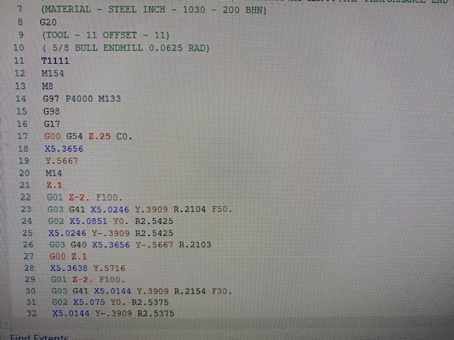
M01what I am doing wrong ,did I am change something ????
-
On 2/10/2024 at 11:07 AM, crazy^millman said:
+1 Above suggestion or 3D HST Blend or Unified(Morph Between 2 Curves) in 3 Axis , Unified(Parallel) in 3 Axis.
I am use morph
-
1
-


C-axis Face contour won't work with y axis
in Industrial Forum
Posted
so you can cwich change for Y out pu on this settings