


mirek1017
-
Posts
888 -
Joined
-
Last visited
Content Type
Profiles
Forums
Downloads
Store
eMastercam Wiki
Blogs
Gallery
Events
Posts posted by mirek1017
-
-
1 minute ago, Aaron Eberhard said:
Aren't these the same place?
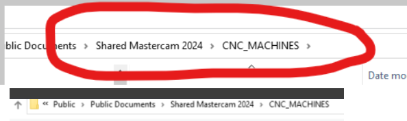
Click up on the the bar with the folder name, and make sure it looks like this:

the 1s t picture is when I am open physically shared mastercam 2024 cnc machines folder
the 2nd picture is when I open from my mastercam 2024 like this


nothing there
-
2 minutes ago, Aaron Eberhard said:
Are you selecting all previous versions allowed when migrating?
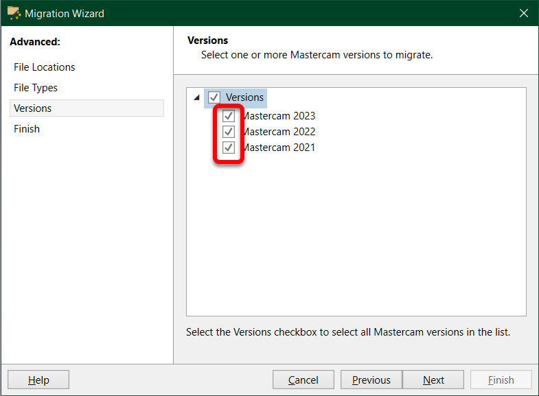
ok ,I can try this ,but when I open my shared folder my machine is there

when I am do the same thing from 2024 is nothing there

-
2024 update some what I am not use any more (***like those x9 **)but not not this what I want to use now
What I need tot do ,I need to manual select folder off mcx 20203
-
Hello All.
I am use Migration Wizard to covert my all file from from 23 to 24 mastercam ,on 24 mastercam dont shows all off my machines ,how I can fix this
this is 2023 folder

I do not has this machine in 2024 folder

looks like I am not has half off the machines on 2024
-
On 11/3/2023 at 1:37 PM, Kyle F said:
I mostly program using dynamic work offsets across multiple planes so I only have to set 1 work offset. I mainly program for a haas UMC-500 so as you can imagine it's not the most accurate in 3+2,.. I've never used tooling balls for locating like shown but I will CERTAINLY keep it in mind if I ever have to hold a true position and would like a reference/locating feature
I do not have dynamic work offset on my machines ,I know some people use sample macro calculation ,but I am never try it .
-
I use tooling balls...if I have a tombstone that will need to have angles picked up I make sure I add a toolball location that I can easily reference.
I dont understand ,can you posting some video ?
-
Hello all ,I hope I can explain my question

I am program HMC ,one part only ,the was 2 operation on it .
On lest operation I want to make side hole ,so this is my front plane and part view


I want to rotate my table 75 deg and drill port like this

 Can I use this number for calculation new X and Z position ?
How I can calculate this numbers ?I am not programing from center of rotation so I was wondering there is some method ?
for now I do like this

Rotate table ,Y will be the same and I can take point from right edge
I thing I has to find out center of table rotation ,did I am write ?
-
I am use solid from level 1 and mastercam shows solid what I am not selected

-
58 minutes ago, Murdock said:
Following, because I just came here to ask pretty much the same question. I have a model that imports as all surfaces. I was able to turn one area of the part into a closed solid body, using the solids from surfaces function, but the others are still open sheet solids. And if you think Mcam verify looks a little weird, you should see what Vericut does with that....
I am try my stsl one more time and rename and work now
Just now, mirek1017 said:I am try my stsl one more time and rename and work now

-
 1
1
-
-
Hello All
I am create my stock from stl .file and when I am veryfy looks like stock is empty inside ,how I can fix this ?
thank you

-
1 minute ago, crazy^millman said:
Never stop a stock model that way. Save the file and close Mastercam that has never worked for me and I test it on every release.
Thank you Ron for reply ,this not stock model ,this is my toolpath calcualtion
-
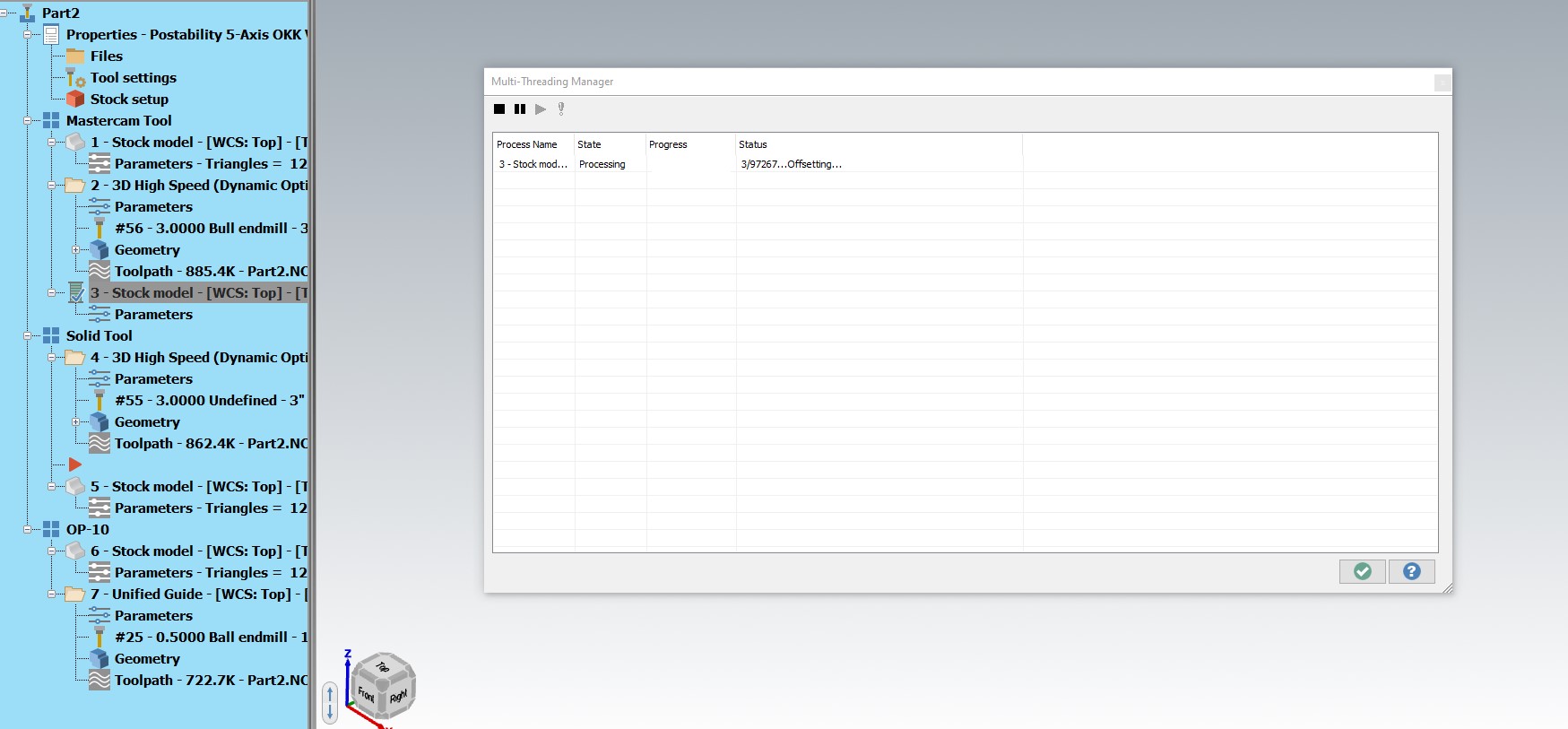
What I can do when mastercam calculate toolapth and stock and wont go thru and I cant stop my operation ?
my sample ,stock on 81 % like this

and when I want to stop it it is freeze least 45 minutes like this

-
Hello ,how activate chaining similar option on mastercam 2024 ?

-
31 minutes ago, JoshC said:
if you need even better quality (at the expense of performance) you can make a more advanced setting change by doing the following.
1. go here C:\Users\(NAME)\Documents\My Mastercam (VERSION)\Mastercam
2. Duplicate the MastercamSimulatorDefaults.xml , then rename it to something like HighPrecisionMastercamSimulatorDefaults.xml
3. Right click the file and choose edit, then change the Force 5 axis option to True and also adjust the Precision Factor from 1 to 4 maximum.
4. then in verify, choose file --> defaults -- Open Defaults, choose your high precision file, and now your verify will be more precise and accurate looking, at the expense of some performance
Thank you I will try this
-
1 hour ago, crazy^millman said:
He was talking about in the Verify Window not in the Mastercam session.

Another thing Precision is control here not what you were showing. That will not be something that requires saving and where having that in the QAT for Verify is helpful.
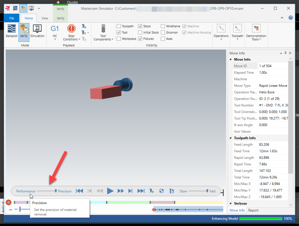
Yes ,that is what I looking for ,thank you Ron
-
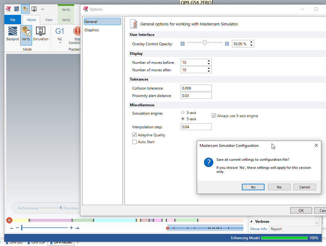
11 minutes ago, gcode said:
drag the slider all the way to the right
The File/Options... check the "Always use the 5-axis engine" button
Click OK, the select Yes to save a new default file
I do no see it anything hehe

-
HELLO , I am start play on mc 2024 ,haw I can fixing the quality my verify ?

also ,how I can get this bare set up default for high quality ?

thank you
-
37 minutes ago, crazy^millman said:
Something has to define the pfn logic. In MPLMASTER there is this switch:
tseqno       : 2     #Output sequence number at toolchanges when omitseq = yes
                     #0=off, 1=seq numbers match toolchange number, 2=seq numbers match tool number
We then search the post to find where and how it was used:
ltlchg$          #Toolchange, lathe
. section not shown
. section not shown
. section not shown
. section not shown
      if not(synch_flg & tool_op$ = 67),     #Suppress tool output if cutoff during part xfer
        [
        if omitseq$ = 1 & tseqno > 0,
          [
          if tseqno = 2, n$ = t$
          pbld, *n$, [if home_type = -1, *sgcode], *toolno, e$
          ]
        else, pbld, n$, [if home_type = -1, *sgcode], *toolno, e$
        ]
mtlchg$ #Toolchange, mill . section not shown . section not shown . section not shown . section not shown if omitseq$ = 1 & tseqno > 0, [ if tseqno = 2, n$ = t$ pbld, *n$, [if home_type = -1, *sgcode], *toolno, e$ ]pheader$ #Start of file pheader_custom if tseqno = 1 & omitseq$ = 1, [ seqno$ = 1 seqinc$ = 1 n$ = seqno$ ]Then from there we can see what variables where defined and how we want to adapt it to the post we are using.
I am find this in my post
# --------------------------------------------------------------------------
# Motion NC output
# --------------------------------------------------------------------------ptool_insp #Tool inspection point
#Modify following lines to customize output for tool inspection points
if posttype$ = two, #Lathe tool inspection point
[
pcool_off #Coolant off before tool inspection
pbld, n$, pnullstop, e$
pbld, n$, scoolant, e$
if prmcode$ = 29999, #Only output tool insp comment if one was entered with this insp point
[
sparameter$ = ucase(sparameter$)
pbld, n$, *sm00, sopen_prn, sparameter$, sclose_prn, e$
]
else, pbld, n$, *sm00, "(INSPECT TOOL)", e$ #Output just the stop if no comment
pbld, n$, *sgcode, *toolno, e$ #Restate tool number
pbld, n$, pfsgplane, #Restate plane code
if css_actv$, #Restart Spindle
[
if css_start_rpm, prpm, pcssg50, pcss #Direct RPM startup for programmed CSS
else, pcssg50, pcss #NO RPM start - just output the CSS
]
else, prpm #Direct RPM was programmed
result = force(feed) #Force output of feed next time it's called for output
prv_gcode$ = c9k
prv_workofs$ = c9k
pinsp_cool_on #Coolant on after tool inspection
pbld, n$, scoolant, e$
]
else,#Mill tool inspection point
[
pcool_off #Coolant off before tool inspection
pbld, n$, scoolant, e$
pbld, n$, pnullstop, e$
pbld, n$, sm00,"(CAUTION POST GENERATING MOTION FOR TOOL INSPECTION)", e$
pbld, n$, *sg28ref, "U0.", [if y_axis_mch, "V0."], "W0.", e$
pbld, n$, sm00, "(INSPECT TOOL)", e$
pbld, n$, *sgcode, *toolno, e$ #Restate tool number
pbld, n$, pfsgplane, e$ #Restate plane code
pspindle
prpm #Restart Spindle
pinsp_cool_on #Coolant on after tool inspection
pbld, n$, scoolant, e$
pbld, n$, *sgcode, pwcs, pfxout, [if y_axis_mch, pfyout], pfzout, e$
]prapidout #Output to NC, linear movement - rapid
if lathecc = zero,
[
if millcc_flag & (abs(cuttype) = four | abs(cuttype) = two) & cutpos2$ = zero, #Polar interpolation is active & Y-axis subs or Right face or Left face & before start point of operation geometry
[
if abs(cuttype) = four, #Y-axis substitution, output C first on separate line
[
pcan1, pbld, n$, pexct, psgcode, pcout, e$
pbld, n$, pexct, pxout, pyout, pzout, pscool, strcantext, e$
]
else, #Right or Left face cut, output Z last on separate line
[
pcan1, pbld, n$, pexct, psgcode, pxout, pyout, pcout, pscool, strcantext, e$
pbld, n$, pexct, psgcode, pzout, e$
]
]
else,
[
pcan1, pbld, n$, psgplane, pexct, psgcode, psccomp, pwcs, pxout, pyout,
pzout, pcout, pscool, strcantext, e$
]
]
else, #Lathe canned turning cycle
[
pcan1, pbld, n$, pexct, psgcode, psccomp, pxout, pyout, pzout, pcout, pscool, strcantext, e$
]
if force_feed, result = force(feed) # Force output of feed next time it's called for output
if rpd_typ$ = 7, ptool_insp #Tool inspection pointplinout #Output to NC, linear movement - feed
pcan1, pbld, n$, psgplane, sgfeed, pexct, psgcode, psccomp, pwcs, pxout,
pyout, pzout, pcout, pfr, pscool, strcantext, e$
if rpd_typ$ = 7, ptool_insp #Tool inspection pointpcirout #Output to NC, circular interpolation
pcan1, pbld, n$, psgplane, sgfeed, pexct, psgcode, psccomp, pxout,
pyout, pzout, pcout, parc, pfr, pscool, strcantext, e$ -
4 minutes ago, crazy^millman said:
Something has to define the pfn logic. In MPLMASTER there is this switch:
tseqno       : 2     #Output sequence number at toolchanges when omitseq = yes
                     #0=off, 1=seq numbers match toolchange number, 2=seq numbers match tool number
We then search the post to find where and how it was used:
ltlchg$          #Toolchange, lathe
. section not shown
. section not shown
. section not shown
. section not shown
      if not(synch_flg & tool_op$ = 67),     #Suppress tool output if cutoff during part xfer
        [
        if omitseq$ = 1 & tseqno > 0,
          [
          if tseqno = 2, n$ = t$
          pbld, *n$, [if home_type = -1, *sgcode], *toolno, e$
          ]
        else, pbld, n$, [if home_type = -1, *sgcode], *toolno, e$
        ]
mtlchg$ #Toolchange, mill . section not shown . section not shown . section not shown . section not shown if omitseq$ = 1 & tseqno > 0, [ if tseqno = 2, n$ = t$ pbld, *n$, [if home_type = -1, *sgcode], *toolno, e$ ]pheader$ #Start of file pheader_custom if tseqno = 1 & omitseq$ = 1, [ seqno$ = 1 seqinc$ = 1 n$ = seqno$ ]Then from there we can see what variables where defined and how we want to adapt it to the post we are using.
I hope I can get only .00001% your knowledge
-
23 minutes ago, tornero32 said:
I sincerely Apologize for interrupting your question. You were going to get help from the best, I'm sorry.
I read here that you have to have Stepup Check. if you do not want to do the stepup , Stepup and stepdown should match. I see your part has an angle stepup
Should be better for the finish tool.
np

did you know how off this higlits solid option ? I am try this seeting and didnt work

-
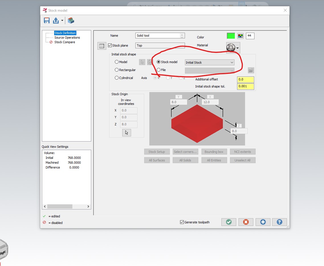
5 minutes ago, tornero32 said:
I have to use my previous Stock model.
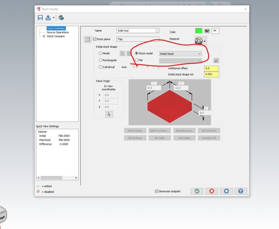
Like this
It's been working for half an hour and it doesn't do anything.

Try change path tolerance and toolshape tolerance on bigger
-
21 minutes ago, crazy^millman said:
Look at the old MPLMASTER post it has the process already defined in it.
so this work the same way in lathe post ?
I can find this in my lathe post
pbld, *pfn, *t$, "M6",e$
-
21 minutes ago, tornero32 said:
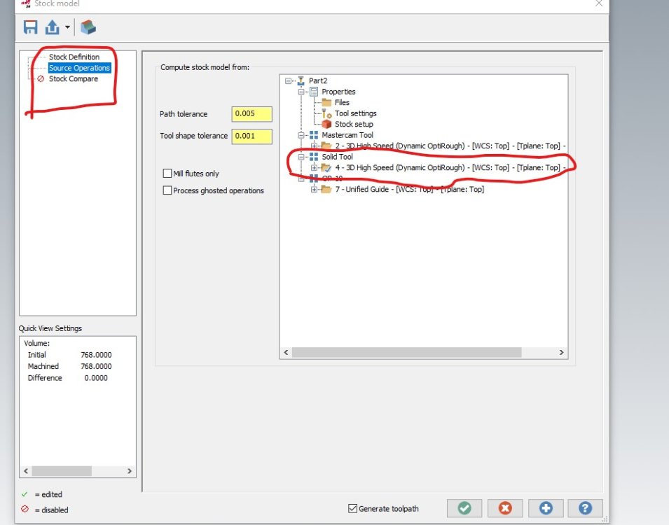
When I use a solid model for my tool on Mastercam 2024 update 3 I cannot create a Stock model.
I use Optirough all the time then stock model, after that Optirough but this time with rest material with smaller tool , one other operation and select stock model,
after that I create another stock model using those operations as source operations and I cannot get a new stock model'. If Iuse a regular tool it works.
I don't know if I explain myself. If not, I'll send pictures later on.
Coul you please create I stock model after that operation using that operation as source operation and let me know if you can create the stock model operation.
When you have time. it doesn't work for me 2024. are you on 2024? if I use a regular tool it works, I tool from Mastercam.
Thank you.
try this


-
1
-
-
2 minutes ago, AHarrison1 said:
I have mine set so N# follows T#
N1 (OD 80 DEG)
G18 G20 G40 G54 G80 G99
G00 G53 X0. Y0. T0
T101
G40 G54 G80 G99
M155
M08
G50 S3500
G96 S450 M03
G00 X2.1 Y0. Z0.01
M88
M05
M89
G00 G53 X0. Y0. T0
M01N3 (OD 55 DEG)
G18 G20 G40 G54 G80 G99
G00 G53 X0. Y0. T0
T303
G40 G54 G80 G99
M08
G50 S3500
G96 S450 M03
G00 X1.5787 Y0. Z0.0072
M88
M05
M89
G00 G53 X0. Y0. T0
M01yes something like this


Machine definision
in Industrial Forum
Posted
this is when I am open my machine folder from mastercam
and this is the same when I open my folder outside of mastercam