David Conigliaro CNC Software Inc.
-
Posts
335 -
Joined
-
Last visited
Content Type
Profiles
Forums
Downloads
Store
eMastercam Wiki
Blogs
Gallery
Events
Everything posted by David Conigliaro CNC Software Inc.
-
 Optirough_Rest_Problem_2020.mcam
 -
This will fix things in OP4
-
Did you start the file with an imported file?
-
Yes, the 19 bullet points in the above video explanations and some write ups in the What's New document installed with Mastercam 2020. The videos above are really good!
-
Changes to chaining go far beyond the interface in 2020. Mastercam 2020 - Chaining Enhancements 1 Refreshed dialogs Solids - Merged 'Edge' and 'Linked edges' modes into single 'Edges' mode Solids - Edges - Can now start a new chain when a disconnected edge is selected Solids - Edges - Added previous branch support Solids - Edges - 'Unselect' now removes last chain, instead of last entity Solids - Edges Improved default next branch direction, first checks for tangent, then Tplane Wireframe - Guided chaining - Added previous branch support Wireframe - Guided chaining - Improved default next branch direction, first checks for tangent, then Tplane Wireframe - Guided Chaining - Can now start a new chain when a disconnected entity is selected Mastercam 2020 - Chaining Enhancements 2 Solids - Can now create partial loop chains on multiple solid bodies in the same session Solids - New tangent edge propagation with tolerance Wireframe - New tangent entity propagation with tolerance Mastercam 2020 - Chaining Enhancements 3 Solids - Added support to edit existing chains Wireframe - Added support to edit existing chains Mastercam 2020 - Chaining Enhancements 4 Configuration - Colors - New 'Chain' and 'Chain highlight' color Configuration - Chaining - New settings to set chain line style and line width General chain display enhancements Mastercam 2020 TP4 - Chaining Enhancements 5 Solids - Convert Face chains to Loops Solids - Convert Loop chains to Edges
-
Yes, I can understand that. On another note. You mentioned you stay away from stock models due to processing time. Stock models process pretty fast when tolerances are aligned. I can see the time maybe taking long if you never adjust the stock model Path tolerance from default, especially on large files. I created a very clean stock model from OP7 and OP8 in less than 2 minutes using the initial stock shape provided on level 5. the Path tolerance was set to .015 which is still far less than your.05 stock to leave. Remember, stock models are captured in the file so they are safe for long term archiving. I also noticed someone put a suggested workaround in that file to use a stock model (OP10) that references your STL file after it was imported onto level 200 as a Mesh entity. That too is a viable solution as you will now have the STL data preserved as it is saved locally on level 200 and a clean stock model from it as referencing a Mesh entity or external STL goes through a clean up process on the triangle data during stock model processing. Your STL was not clean and watertight saved out of verify, that is why OP9 gouges as OP9 simply references the troublesome external STL file. OP11 is clean because the troublesome STL file was brought in as a Mesh entity on level 200 (which is still troublesome) and then selected for Stock Model 10. Upon processing Stock Model 10 the selected troublesome Mesh data was cleaned up, that is why OP11 does not gouge. Hope this helps some.
-
Thank you, I'll start with looking into R-18569. I'll have a read on that ticket as well...
-
Could you provide any Request or Defect numbers from your 2 concerns you contacted us with? I would like to look at your part files relating to the Rest roughing and scallop rest pass concerns.
-
Face - Dynamic Mill Help
David Conigliaro CNC Software Inc. replied to Rotary Ninja's topic in Industrial Forum
It all boils down to understanding how your tools are consumed by toolpaths while realizing defining tools accurately is paramount. Hopefully you all see how we try to balance flexibility against not making the software too flexible which can introduce confusion. We don't want to go crazy adding all sorts of exceptions. A tool can't behave this way over here, that way over there, another way somewhere else. Hard to learn and teach. We chose to make Face Mill behave oneway relative to it's cutting diameter and gave it one exception by supporting the 2D Contour Chamfer toolpath recently as we felt there was good continuity there, facing blocks and cleaning up the edges go hand in hand. -
Face - Dynamic Mill Help
David Conigliaro CNC Software Inc. replied to Rotary Ninja's topic in Industrial Forum
We have the 3 main generic tool shapes for 90% of work, Flat, Bull and Ball. Then we have special tool types like the Face mill, used for Facing blocks and also useful for chamfering the block after facing. Yes, the 2D Contour set to 'chamfer' on the cut parameter page will comp accurately to a Face mill with chamfers. Those two things make good sense for Face mills, other than that you have to go a different route using Flat, Bull or ball. -
Face - Dynamic Mill Help
David Conigliaro CNC Software Inc. replied to Rotary Ninja's topic in Industrial Forum
You use a bull mill if you want to accurately comp the side of the tool, like in a Contour toolpath, yes. -
Face - Dynamic Mill Help
David Conigliaro CNC Software Inc. replied to Rotary Ninja's topic in Industrial Forum
Well said gCode, same thing goes for software development. It can be dangerous to change a legacy behavior affecting potentially 10's of 1000's of users. with 100's of 1000's of files out there. -
Face - Dynamic Mill Help
David Conigliaro CNC Software Inc. replied to Rotary Ninja's topic in Industrial Forum
I'm sure you all already know this, but just reinforcing. Safest thing to do is define your Face Mill for facing as you get clean overlaps and such and define the same tool as a Flat or Bull nose endmill. As long as you use the same Tool# in Mastercam you can safely use the single face mill on the machine. -
Face - Dynamic Mill Help
David Conigliaro CNC Software Inc. replied to Rotary Ninja's topic in Industrial Forum
We also must way the impact of such changes. Changing a tool comp is very serious, massive impact, as it will destroy all existing files upon a regen in the version of Mastercam with the change. We have not received a high number of complaints on this comparatively speaking. But that doesn't mean a change is not justified, we just have to tread very lightly with tool comp changes. -
Face - Dynamic Mill Help
David Conigliaro CNC Software Inc. replied to Rotary Ninja's topic in Industrial Forum
Yes gcode, I am currently discussing if we should be using secondary diameter for face mills in toolpaths other than facing with my Mill Team. Stay tuned. It's been this way for decades with very few complaints so it will be hard to get traction for fear of messing up regens in legacy files! -
Face - Dynamic Mill Help
David Conigliaro CNC Software Inc. replied to Rotary Ninja's topic in Industrial Forum
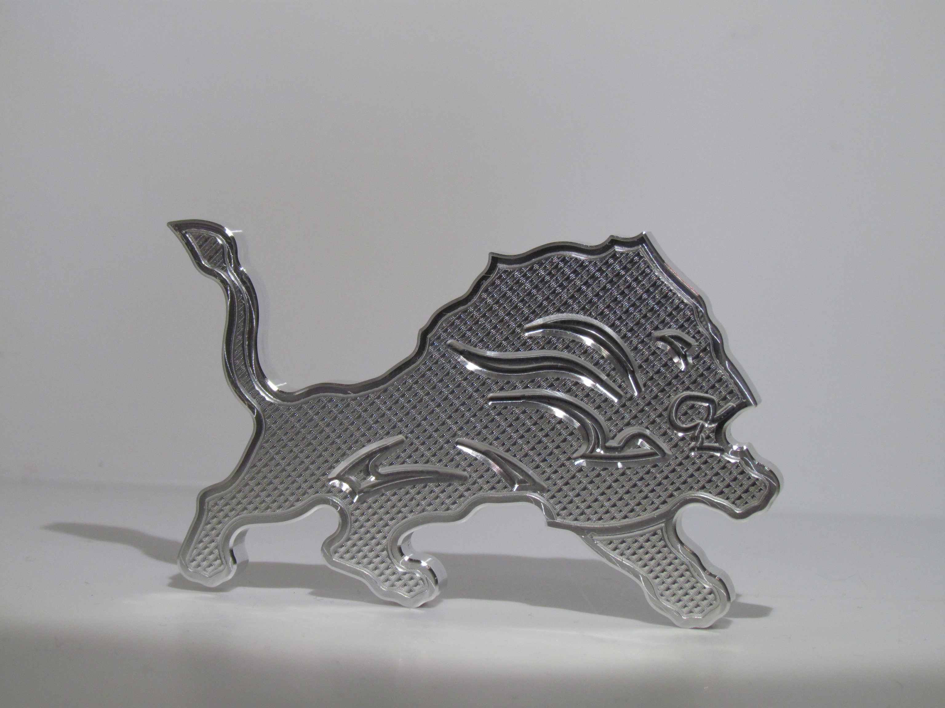
Some times, depending how you are using a tool, you must define it as two different tool types. For Example. I had this 3/4in all in one type tool. I could chamfer, spot drill and side mill with it. I used it to Spot drill in my part file at Tool #6. So I initially defined it as a Spot Drill tool type. Later, I was using our 2D Engrave toolpath and wanted to us it as an engraving tool as it could very well handle it. The tool was already in the carousal and would do a good job. I selected it and received an error, no toolpath output. Engrave did not like the Spot Drill tool type. So I created an Engrave Tool type and assigned Tool #6. Yes, I received a duplicate tool # warning but I new what I was doing and Mastercam allowed me to define two Tool#6 tools that Mastercam would consume very differently even though it was the same single tool on my machine. I was milling Aluminum billet Detroit Lions magnets!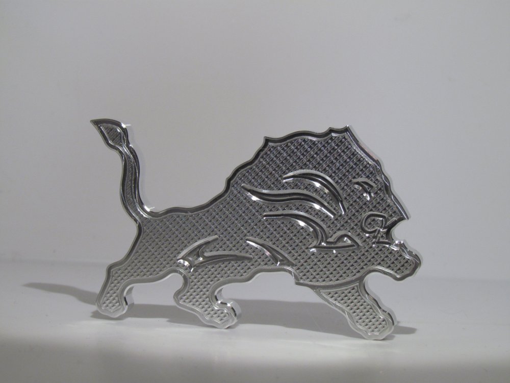
-
Face - Dynamic Mill Help
David Conigliaro CNC Software Inc. replied to Rotary Ninja's topic in Industrial Forum
Thank you Josh, you stated my entire point of this thread. We must define tools accurately as Mastercam will intelligently apply them based on definition. Did you know...there are actually two very different processing logics behind Dynamic technology. One based on flat sharp endmills and one based on Bull nosed endmills. Ball cutters are simply treated like Flat sharp endmills. Using a Flat or a Bull can affect OptiRough processing time, there is more happening with Bull nosed to ensure no material islands or nubs are left behind... -
Face - Dynamic Mill Help
David Conigliaro CNC Software Inc. replied to Rotary Ninja's topic in Industrial Forum
I can look into the face mill and Contour interaction.. -
Face - Dynamic Mill Help
David Conigliaro CNC Software Inc. replied to Rotary Ninja's topic in Industrial Forum
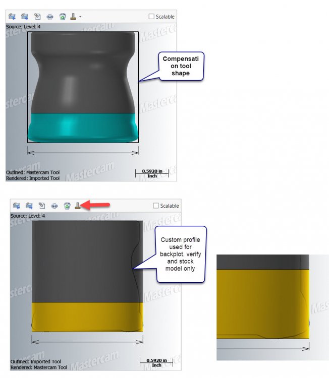
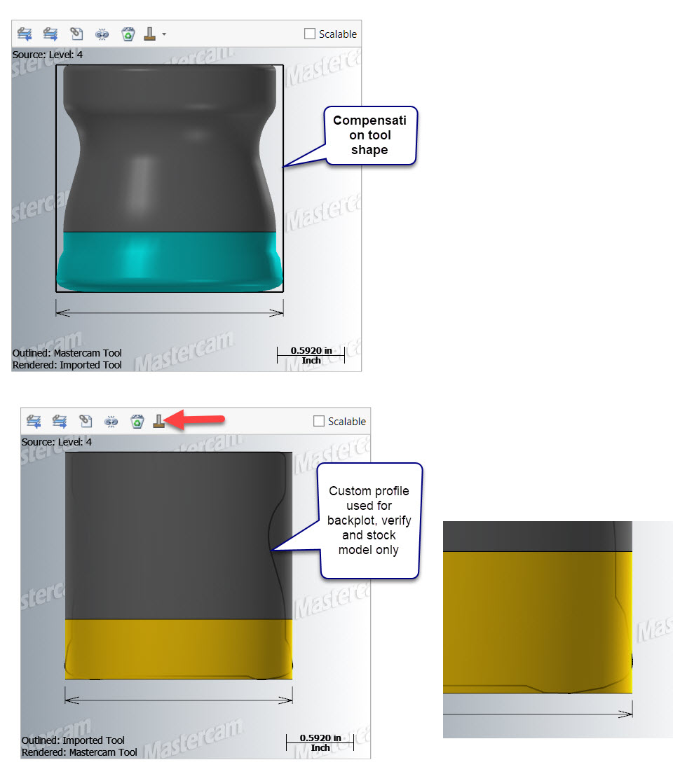
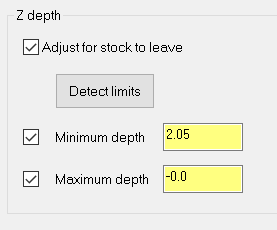
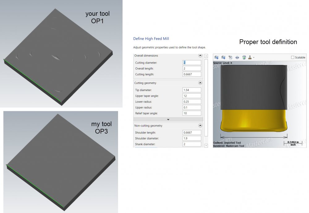
Here's your original tool leaving material. You basically defined a flat endmill for toolpath compensation (yellow) and told Mastercam to use the custom profile (aqua) for backplot, verify and stock model as that would truly represent what will happen at your machine. Nothing is wrong here. Stock Model, verify, and your machine all show leftover material, that is correct.
-
Face - Dynamic Mill Help
David Conigliaro CNC Software Inc. replied to Rotary Ninja's topic in Industrial Forum
Mastercam does what you ask. You asked it to use a sharp endmill shape and you loaded a different shaped tool at your machine. -
Face - Dynamic Mill Help
David Conigliaro CNC Software Inc. replied to Rotary Ninja's topic in Industrial Forum
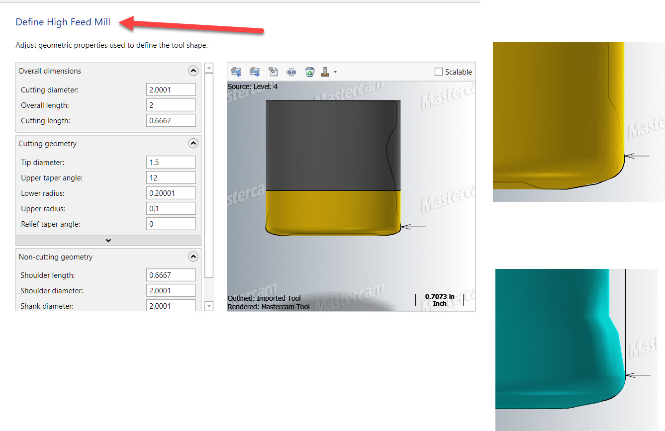
regardless, you used a sharp face mill with a custom profile, Mastercam never comps to the custom profile. At least define your face mill with a full radius and try to get it close to your actual tool profile. Here's your tool with a tweak. Look at the attached file, two good toolpaths with your tool tweaked and my highfeed, both correct. There are no problems here against facing. dynamic face_DC.mcam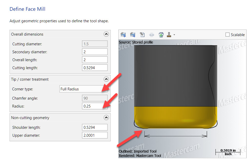
-
Face - Dynamic Mill Help
David Conigliaro CNC Software Inc. replied to Rotary Ninja's topic in Industrial Forum
-
Face - Dynamic Mill Help
David Conigliaro CNC Software Inc. replied to Rotary Ninja's topic in Industrial Forum
-
Face - Dynamic Mill Help
David Conigliaro CNC Software Inc. replied to Rotary Ninja's topic in Industrial Forum
There should be nothing wrong with the facing toolpath when tools are defined correctly and arc fit tolerances are reasonable. -
Face - Dynamic Mill Help
David Conigliaro CNC Software Inc. replied to Rotary Ninja's topic in Industrial Forum
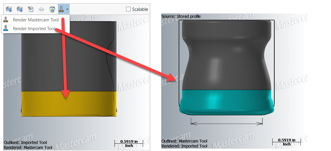
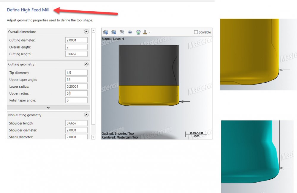
You did not define a highfeed cutter? You defined a Face mill cutter to look like a highfeed cutter. If you use the actual HighFeed tool type we take care to comp accurately to the bottom highfeed profile. Mastercam is comping your tool as defined like a sharp endmill, the picture shows it on the definition page. Blue flutes represents your profile shape, yellow flutes represent what Mastercam uses to comp.