David Conigliaro CNC Software Inc.
-
Posts
335 -
Joined
-
Last visited
Content Type
Profiles
Forums
Downloads
Store
eMastercam Wiki
Blogs
Gallery
Events
Everything posted by David Conigliaro CNC Software Inc.
-

Face - Dynamic Mill Help
David Conigliaro CNC Software Inc. replied to Rotary Ninja's topic in Industrial Forum
At least we know why the nub is there -
Face - Dynamic Mill Help
David Conigliaro CNC Software Inc. replied to Rotary Ninja's topic in Industrial Forum
-
Face - Dynamic Mill Help
David Conigliaro CNC Software Inc. replied to Rotary Ninja's topic in Industrial Forum
-
Face - Dynamic Mill Help
David Conigliaro CNC Software Inc. replied to Rotary Ninja's topic in Industrial Forum
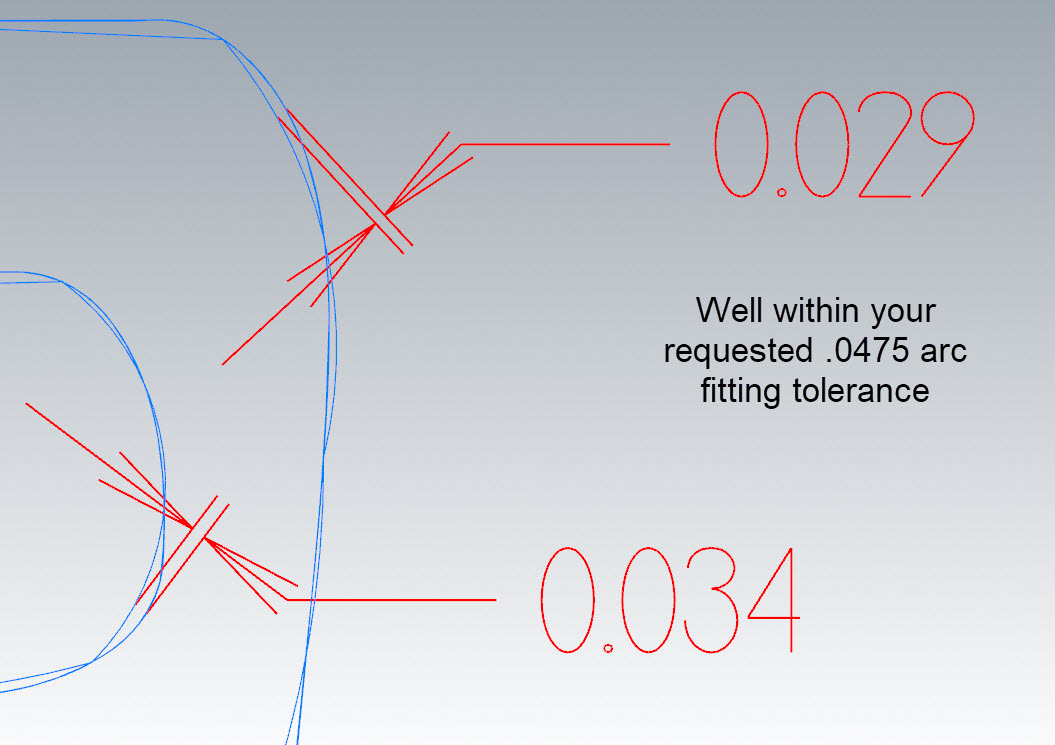
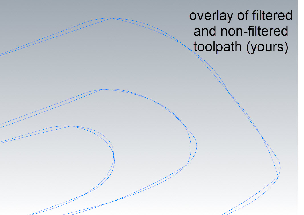
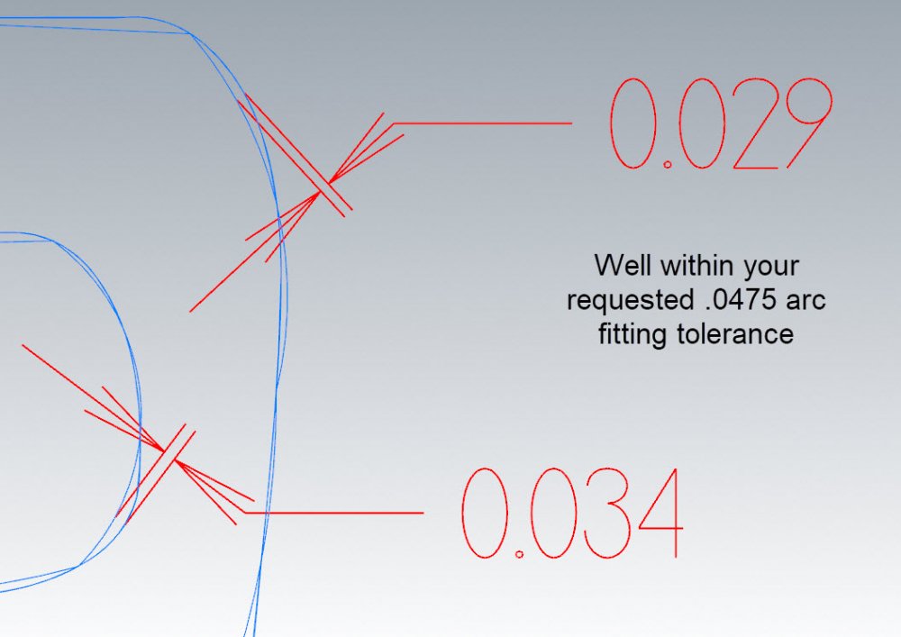
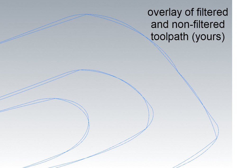
Look at this image of the aggressive filter. Top is your file as sent to me.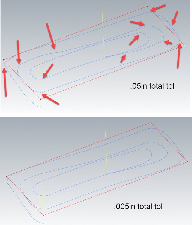
-
Face - Dynamic Mill Help
David Conigliaro CNC Software Inc. replied to Rotary Ninja's topic in Industrial Forum
You are causing this problem with your very aggressive arc filter settings. Look at how compromised your motion is, you should notice sharp corners and such. You actually have your arc filter set to deviate by as much as .0475in! Yikes! That's the problem. You're giving 95% of your total tolerance of .05in to the arc filter to work with.You allowed the toolpath to deviate by as much as .0475in from the original accurately calculated motion. I set total tolerance to .005in (still loose) and gave the arc filter 50% to work with. I still got plenty of arcs and no nub. -
Face - Dynamic Mill Help
David Conigliaro CNC Software Inc. replied to Rotary Ninja's topic in Industrial Forum
Thank you -
Face - Dynamic Mill Help
David Conigliaro CNC Software Inc. replied to Rotary Ninja's topic in Industrial Forum
I cannot reproduce this on my examples. My examples are not square, you haven't said anything about shape. Are you talking about a simple perfect square block? I tired stepovers from 10-90% with no problems. In the end we can only troubleshoot with real files, real examples. Please send a file. -
Face - Dynamic Mill Help
David Conigliaro CNC Software Inc. replied to Rotary Ninja's topic in Industrial Forum
Can someone share the file in question. I need to see how the face mill is defined. Are the face mill inserts 45 degrees or vertical, etc... -
Yes, thanks Ron Library can be found here. Emuge adds tools faster then this library is updated. https://community.mastercam.com/techexchange#files
-
In MC2017, you can define the Emuge Lens Form tool as a Highfeed Mill tool and use the tool in toolpath/surface paths (classic and 3D HST). More to come in 2018 To do so in 2017, set the Highfeed Mill Cutting diameter, Lower radius and Upper radius. Set the Tip diameter to zero. Leave the Lower Taper angle (hidden) set to zero. Set the Upper Taper angle from this equation: Upper Taper angle = inverse sin of (( 0.5 * Cutting diameter – Upper radius) / (Lower radius – Upper radius)). Example: For a Cutting diameter of 0.95, Lower radius of 1.0 and Upper radius of 0.1, we have: Upper Taper angle = inverse sin of (( 0.5 * 0.95 – 0.1) / (1.0 – 0.1)) or Upper Taper angle = inverse sin of ( 0.375 / 0.9) or Upper Taper angle = inverse sin of (0.41666) or Upper Taper angle = 24.6243 degrees Sometimes the tool dialog will show an odd image for the tool rendering or will balk at these numbers; if so, just reduce the Taper angle slightly (24.60 say) or give it a really small tip diameter (0.001 say).
-
Good point, I'm forwarding that to our Design team. In the meantime under the advanced tab on the Boolean panel you can disable auto preview.
-
We do not consider it 80% done. Please refrain from personal attacks on the Company, some people really struggle with ADD and might consider your loose use of the term offensive.
-
To expand on what Ben suggests. Make sure your tolerances are loosened up, after all it's just rest material you're after, some of which will be filtered out using your 'adjustment to stock' in the rest toolpath. There isn't much difference between a rest toolpath using a stock model at .001 and a stock model at .01, other than more processing time! Keeping tolerances inline with parts size and complexity is implied here. Use stock model as a targeted tool. In addition to ensuring you only include toolpaths necessary for the desired rest material shape, try starting with a smaller initial stock shape. Isolate the initial stock shape to just the area you are interested in on these big jobs. For example, just create a block in the area you wish to rest and carve your toolpaths into that. I have also created solids using model prep to identify volumes I wanted to rest and used the solids as initial stock shape with not selected toolpaths for carving. Rest machining is just volume machining, it doesn't matter how you get the stock shape.
-
I'm guessing you are not running X9? Or you are using the 'shift' trick out of habit X9 made major changes to selection sensitivity. The 'shift' is no longer needed to select wireframe within a surface or solid face's boundary. In X8 Sketch a rectangle with surface creation on then create a line within the surface edges, X8 will not select the line with shading turned on. Open this file in X9 and you should have no problem selecting the line.
-
Use the 'ctrl' button to temporarily disable the autocursor when you simply don;t want it snapping to anything. 'Shift' click selects a chain of wireframe entities, but did you know it can also select a partial chain? Hold 'shift' select the first entity as if you were chaining to control the direction. While still holding 'shift' click on the last desired entity in your partial chain, release 'shift'. Hold 'alt' to go into vector selection mode. Sketch a string of vectors, Mastercam will select anything they touch upon releasing 'alt' When selecting solid faces in solid selection mode 'shift' will select all tangent faces.
-
Helix Bore~ Finish only?
David Conigliaro CNC Software Inc. replied to jeff's topic in Industrial Forum
Silly trick, but mirroring a 2D Contour ramp in the right or front view about it's center will cut from bottom up. https://mastercam.sharefile.com/d-sd8819c7b76242189 -
Helix Bore~ Finish only?
David Conigliaro CNC Software Inc. replied to jeff's topic in Industrial Forum
We are considering bottom to top cut order for 2D Contour Ramp in 2018. -
jlw - What you are using the stock models for? Why are you creating them?
-
Ultra High Precision Surfacing help.
David Conigliaro CNC Software Inc. replied to chad fisher's topic in Industrial Forum
Long, long shot here, but if you can make them work on your form the 'Wireframe' toolpaths, Swept, Loft, etc..will produce more accurate motion than any mesh machining or direct surface machining technologies can produce. We do have customers cutting lenses with the wireframe toolpaths, they produce the most pure motion. There is no ModuleWorks technology in our 3D High Speed Toolpaths past the Holder tilt. -
Ultra High Precision Surfacing help.
David Conigliaro CNC Software Inc. replied to chad fisher's topic in Industrial Forum
I have no experience with this particular application but I can tell you to not use Surface Parallel for this. Surface High Speed Raster with no filter is well capable if everything else is inline, tool, holder, feeds etc...Yes CAMTool does machine the surface data direct but triangle machining (Mastercam, PowerMill, etc..) can produce the finish you are looking for. You can try Flowline on one of those faces if you want, it machines the surface data direct for comparison. -
Opti Toolpaths not respecting the boundary
David Conigliaro CNC Software Inc. replied to a topic in Industrial Forum
What's up Ron Joining this party.... -
Opti Toolpaths not respecting the boundary
David Conigliaro CNC Software Inc. replied to a topic in Industrial Forum
alright Picard, make it so, send your file along. Stay hard inside boundary and approach stock from outside. That is exactly what OptiRest does. -
Opti Toolpaths not respecting the boundary
David Conigliaro CNC Software Inc. replied to a topic in Industrial Forum
That's the difference that comes from people who machine for a living and those who do it in a lab with Aluminum. -Tim Markoski Ahhh assumption, that explains a lot. I have plenty of time on real machines making real parts. So this is the second unprovoked insult slung my way while I'm trying to help bring understanding. Please excuse my silence moving forward as I gracefully exit this thread...I feel my time can be better spent elsewhere. -Colin - you're still alright at least you are capable of articulating what is needed....and it is coming -
Opti Toolpaths not respecting the boundary
David Conigliaro CNC Software Inc. replied to a topic in Industrial Forum
Stay tuned..... -
Opti Toolpaths not respecting the boundary
David Conigliaro CNC Software Inc. replied to a topic in Industrial Forum
I machine plenty. You are mixing up two concepts. The concept of roughing without telling mastercam the stock shape and the concept of rest roughing when you do tell mastercam the stock shape. Two very, very different worlds, you can't apply the same thinking to both as you are trying to do. What you are explaining above can be provided through rest roughing. I am more than happy to confront all your questions live in a gotomeeting...