


#Rekd™
-
Posts
2,931 -
Joined
-
Last visited
-
Days Won
48
Content Type
Profiles
Forums
Downloads
Store
eMastercam Wiki
Blogs
Gallery
Events
Posts posted by #Rekd™
-
-
12 minutes ago, mirek1017 said:
How I can check this ?
Look inside the machine, if it is a Y axis it will have live tooling. Also look at the tooling cupboard and see if they have live tool heads for it.
-
Without seeing the shape or file I would suggest Scallop or Equal Scallop or Flowline.
-
 1
1
-
-
8 hours ago, cnc nemo said:
I'm not familiar with ziptogo conversion, apparently I need to get acquainted, if there is a link, please share it, I'll see how it's done? As for the postprocessor for this model, there is no one, so far I'm just trying to create a machine model myself for a simulation machine in Mastercam.
Without a post processor this is pointless IMHO.
-
 1
1
-
-
A ziptogo is needed to get the Machine definition, control definition and post processor.
The other option is checking with your reseller.
-
I don't have MC2020 installed. You will need to link a ziptogo of a current file with toolpaths using this machine if anyone will look at it.
-
19 hours ago, cnc nemo said:
In my case, I'm trying to create a configuration where the XYZ and W + 2 axes are rotating CB axes, the problem is in the W axis, this axis works correctly when moving manually, but it is ignored during simulation, only the Z axis moves, that's where I have a problem until I figured it out, can someone tell me who has ever create a configuration of such a machine?
Is your Machine Definition created correctly? Does it show this axis combination?
-
Here is a quick video trimming a solid from a surface.
https://www.dropbox.com/s/7vzt8m4l7wwmugv/Trim Solid To Surface.mp4?dl=0
-
1
-
1
-
-
3 hours ago, TFarrell9 said:
Do you have any videos on how to model this?
I made a quick video on roughly how I created the blade solids.
-
1
-
-
5 minutes ago, TFarrell9 said:
Converting from surface to solid creates a sheet solid, correct?
Not if the surfaces are water tight. You can loosen the tolerance up when doing the surface to solids conversion.
-
1
-
-
1 hour ago, TFarrell9 said:
Do you have any videos on how to model this?
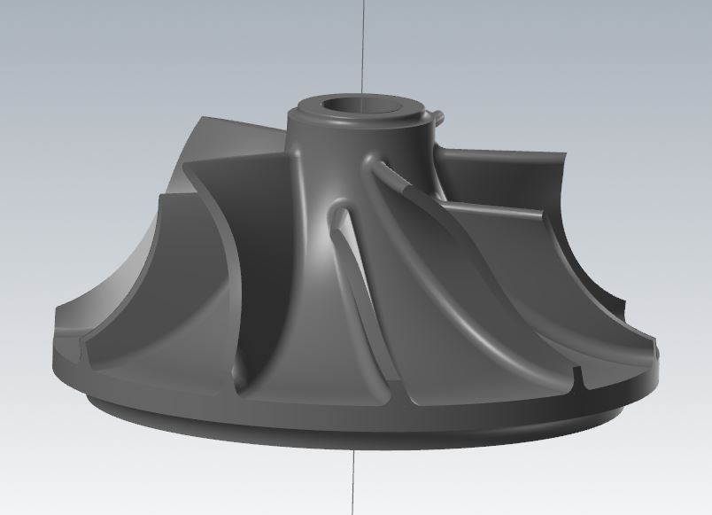
I don't have a video at the moment. I used surfaces for the blades and converted them to solids. I made the center of the impeller from a revolved solid. Then I did a transform rotate of the blades (I made 1 full blade and 1 splitter bladed). Then I use Boolean to join them. Then added the fillets.
I might have had to do a revolved trim on the outside of the blades. The blades have to stick into the center solid to be able to fillet them properly. With having the Model Prep tools it is easy to extend items.
One Solids tool that is really powerful in Mastercam is "Trim by plane" (drop down) "Trim to surface/sheet", most people have never used this. It allows you to cut a solid body to match a complex surface. The surface has to extend past the solid on all sides.
-
1
-
2
-
-
39 minutes ago, Jobnt said:
He's chasing tail in Cuba right now.
Oh to be young and foolish again!!!!!

-
1
-
 3
3
-
-
We were offered TS as an Educational edition (we are an educational facility), they promised the same thing...FREE posts etc....Never materialized.
-
4 minutes ago, Colin Gilchrist said:
I have no idea what you are referring to.
Smaller than small??? :D~~~~
-
9 minutes ago, neurosis said:
I wouldn't mind if it had those things as well.
Or at least solid assembly functionality. It would sure make my job easier. Dynamic transform is great but constraints sure would be nice.
I thought you had or were using TopSolid?
-
4 minutes ago, OVodov said:
Having parametric sketcher would only benefit us as programmers and safe our time.
I disagree, for me it would add time. I can use the model prep to easily alter a solid for my needs. Adding constraints is restrictive for my use.
Obviously we are using it for different purposes.
This impeller was 100% modeled in Mastercam.
-
2
-
-
I like the fact it is a direct modeler, for what I do it works very well.
It is not an engineering software like a full version of NX or Catia.
-
On 6/30/2023 at 9:26 AM, neurosis said:
Wouldn't it be nice if MC had a decent sketcher for solid modeling?
Mastercam is excellent for modeling.
-
I made a video for you, see if this helps. You did not share a Mastercam file, only the solid model.
https://www.dropbox.com/s/nsfz502y0r4vp8b/Surface Pocket.mp4?dl=0
-
1
-
-
1 hour ago, Maximusss said:
I have tried this for 2 hours already but no luck!!
You might want to consider some training.
In-House Solutions has made their training materials available for free.
Caminstructor offers great content as well.
-
3
-
-
Welcome to the forum!
More information is required! What version of Mastercam? What Machine are you programming?
Most important is linking a valid Mastercam file so people can offer the correct solutions without guessing.
-
1
-
-
Another idea is to run the code through the graphics settings on the HAAS control. This should pick up any code issues.
-
2
-
-
Why not use Swarf?
-
Laughing my a$$ off at this one!!!!!
Contact your reseller.
-
1
-
1
-
-
Not dynamic but this gives some information.
-
1
-
1
-
live tooling
in Industrial Forum
Posted
Those Y keys don't look used, I assume it is not a Y-Axis machine.
Rotate the turret until one of the round hole stations is the current tool. Then look into the hole for a drive shaft.