Jeremy Grigsby
-
Posts
146 -
Joined
-
Last visited
Content Type
Profiles
Forums
Downloads
Store
eMastercam Wiki
Blogs
Gallery
Events
Everything posted by Jeremy Grigsby
-

Output the Work Offset values in program header
Jeremy Grigsby replied to rogkick's topic in Industrial Forum
Upon reading you post again, I imagine you must have been talking about outputting from mastercam. I guess you could always do a manual entry? -
Output the Work Offset values in program header
Jeremy Grigsby replied to rogkick's topic in Industrial Forum
You can use a G10 to automatically write to any work offset or tool offset values. G90 G10 L2 P1 X5. Y6. Z7. This overwrites g54 with the specified values G91 G10 L2 P1 X.1 Y.1 Z0. This incrementally updates G54 by .100 in x and .100 in y G91 G10 L11 P2 R.001 This adds to the tool length wear offset(L11) of tool 2(P2) by the value of 0.001(R.001) L10 tool length offset L11 tool length wear offset L12 tool radius offset L13 tool radius wear offset specifying G91 is an incremental update to value, G90 replaces with specified value I don't know if this is what you were looking for. -
Mounting rotary 4th axis on a sine plate.
Jeremy Grigsby replied to Jeremy Grigsby's topic in Industrial Forum
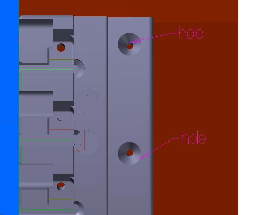
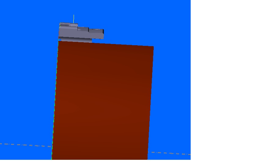
Look guys, I understand work planes. I am just wondering since the rotary table would be rotating on an axis that is tilted in z, will it post out appropriately? The part is not out at the diameter it is drawn in. The holes are equidistant from the end face of the parts, but different distances from y centerline. So I believe rotating on a tilt will make xyza different for each hole. Now that I think of it, I dont think there is any way to put the holes in so the are perpendicular because of the part being mounted at a lower diameter. I think I would need a tilt head to acheieve the right angle. I'm attaching a file if any of you want to take a look. The holes point to a different centerline than the rotary axis. ANGLED HOLES.MCX-6 -
Mounting rotary 4th axis on a sine plate.
Jeremy Grigsby replied to Jeremy Grigsby's topic in Industrial Forum
Any ideas? -
I have a mill with a rotary table aligned with the x axis. I have some round segment parts i am doing that are mounted to the rotary. Most of the work on the part is just work that is perpendicular to the outside diameter of the part. There are a couple holes that need to be drilled @ 2.75 degrees off the z axis. Our plan is to mount the rotary on a sine plate at 2.75 degrees, still aligned with the x axis. The yz 0 point is the centerline rotation of the rotary axis. The part we are cutting is a bigger diameter than the fixture it is mounted on, so the centerline is not the same as the rotary. All that information given(I hope I've answered any questions up to this point) Can I tell mastercam that my rotary is at a 2.75deg angle so the holes that i program will rotate and move x,y,z to cut in the right spot? If this part were mounted out at it's finished diameter, it would just be a y0. location (at the right spot in x) but since it has a different centerline, this may not be the case. We are on Mcamx6 mu3 with mill level 3 and 5 axis.

-
Can't you just call a G43H1 On our Mori that applies the height offset and it doesn't move anywhere.
-
You need to make sure your part centerline is lying on 0,0. Axis substitution uses your rotation centerline as the Rotary Diameter centerline you enter in the toolpath axis substitution dialog. Your depth under linking parameters should be an incremental depth from the rotary diameter. I can't send you the file because i only have x6 and cant save toolpath to older x2 files. It might help to use "Create curves- all edges" and select the helixed faces. I would just manually delete all but the outside contour curves. It worked better for me than selecting the solid chain.
-
Shift multiple levels to new levels
Jeremy Grigsby replied to Jeremy Grigsby's topic in Industrial Forum
No problem. -
Shift multiple levels to new levels
Jeremy Grigsby replied to Jeremy Grigsby's topic in Industrial Forum
I tried that one. It justs copies all the geometry to one single level. -
I searched some for this and if I missed it, I apologize. Is there any way to cut a group of levels and paste them onto other levels? My example is the part i have drawn is very similar to another I have drawn. I saved the original part as a different name, but all the levels are named in the file. Let's say I am using levels 1-20, and i want to merge the two files. I would like to put them both in the same file because they are mating mold inserts. I want to take level 1-20 and move them to 21-40 before I import the other file so their geometry doesn't overlap on the levels. Is there any way to do this? Jeremy
-
I think they have to be one way paths with depth cuts.
-
Maybe we shouldn't be facing in one direction and that is what they are trying to tell us.
-
X4 setting toolpath too stop for insert change.
Jeremy Grigsby replied to Jeff2005's topic in Industrial Forum
I could be wrong, but I don't think there was an option in x4 to do that. It was added in the x5 release. There may have been a workaround that people had used, but I have no knowledge of that. -
Has anyone else tried to import tools from within the tool manager, either lathe or mill? I try to import tools from either a .mcx or .mcx-5 file, and after it creates the dbtools file it says something like "tool cannot be loaded" or something. I am at home posting before going to work so I can't read it to be sure. Can someone else try importing tools from another file to see if that works? We use this occaisionally to pull tools out for a similar job.
-
X5 Config - Start/Exit C-plane not sticking
Jeremy Grigsby replied to RTcat's topic in Industrial Forum
I us e three icons on my desktop for lathe mill and our miil/turn. I put the config file under the icon startup properties so each icon starts with a different machine loaded, all icons loaded, and construction planes. Now it seems like it won't load the right cplane like it used to. Some people may enjoy loafkng everything manually, but I don't. -
X5 Config - Start/Exit C-plane not sticking
Jeremy Grigsby replied to RTcat's topic in Industrial Forum
I too am having a lot of problems with config files. I can't get some of them to show under current configuration in the system config. It just changes back to something else. Something is wrong with it. -
look on the lower right of the parameters box. It is where lead in and lead out are located. There is a special parameter box for cutoff paths that lets you specify rpm changes at certain radiuses. Can't tell you exactly because i am not at work yet.
-
Mori Seiki NL2000Y/500
Jeremy Grigsby replied to Mike Whitten CAD/CAM Contractors's topic in Industrial Forum
MT Tooling has both axial and radial tooling that are 2:1, So they will run at 12000 rpm. Make sure you factor in about $40,000 for live tooling though. Get double turning holders as well. Use two tools on the same station and use Y axis to move each tool to center. We bought one in March. -
I don't think they put mapps iv on the lathes. We bought a NL2500/700 in March and it has Mapps III. I was at the mori grand opening of their new headquarters and I did see a new lathe with esprit though. Hmm, I don't know now. The screen should be 19" lcd though. It looks from the pictures that it is Mapps III. I guess we could just wait for an answer. Am I rambling?
-
In addition to the material chips, some tool chips in the conveyor.
-
edited because of double post...
-
Yeah. To get a boring bar to only cut the diameter, i usually just choose a finish pass, and modify the lead out to be a short move. I only chain a line at the diameter i want to cut, nothing else. If you chain a bottom of bore, the boring bar it going to try to cut that.
-
why wont my mastercam take a d corodinate in lathe
Jeremy Grigsby replied to treg's topic in Industrial Forum
I use d+z- My chuck is on the left side of my lathe. I don't have to type negative signs when specifying z locations -
If device manager shows two processors, it's probably a single Xeon chip with hyperthreading enabled. I run a dual xeon hyperthread single core system at home and it shows 4 processors in device manager. I really don't think there is any system that will make Mastercam run better. It is designed to be a very slow program. If it is ever rewritten as a true 64 bit multi-threaded app from the ground up it may show some improvement. I try to use verify to check overcut/undercut conditions to stl models on some parts. Sometimes you just resort to hoping it cut right at the machine because its not efficient to use verify. Just keep your fingers crossed or get a better verification software.
-
why wont my mastercam take a d corodinate in lathe
Jeremy Grigsby replied to treg's topic in Industrial Forum
Hmm. you using x now? Mastercam now has plane selection of D+ Z- which allows you to just input the value you want for the diameter in the horizontal line box. The z values you put in are automatically on the left side of your zero. It's actually quite simple and quick.