huskermcdoogle
-
Posts
1,285 -
Joined
-
Last visited
-
Days Won
3
Content Type
Profiles
Forums
Downloads
Store
eMastercam Wiki
Blogs
Gallery
Events
Everything posted by huskermcdoogle
-

custom 5 axis drill toolpath
huskermcdoogle replied to mustardcam's topic in Post Processor Development Forum
It has a $. By definition it's a predefined variable. Not sure if that one exists.... I'm guessing he should possibly be using depth$, but given it's a 5ax post, it's likely not that simple due to mapping.... -
FANUC macro - high speed look ahead
huskermcdoogle replied to MIL-TFP-41's topic in Machining, Tools, Cutting & Probing
Good error proofing there. I used to do this with our routers. I didn't use a program though to store the nominal tool lengths. I just compared the tool length to my Mastercam assembly length in the main program immediately following the tool change. Purely just a verification as to what the tool was programmed and verified to do. That way you never have to go and edit the length file. If something needs to be different, it will catch it by default. I mostly used standard library tools, but sometimes I had to pull tools out a smidgen further, the 1mm + tolerance was pretty much perfect. I also used center comp with ball endmills, and had a check in the post that would make sure I had used center comp on the tool-path, as well as output into the code to check if a -radius value had put in the wear as we still set tools to the tip, I could do it both ways (tip or center) and the post and code would make sure I had set things up to match. Great work. As far as look-a-head. Just make sure it is the first thing after the tool change and it shouldn't be a problem. If it is, just throw a G4 in there. -
Happy to help.
-
Machine utilization
huskermcdoogle replied to YoDoug®'s topic in Machining, Tools, Cutting & Probing
Time for a chip grinder and a pumpback system..... -
Machine utilization
huskermcdoogle replied to YoDoug®'s topic in Machining, Tools, Cutting & Probing
I'm assuming the LT is doing more setups, and or it takes longer to do them. How many tools are you guys swapping in the turret? Any opportunity to improve on that? What type of jaw system are you running? -
Here is what I would suggest. As you are doing horizontal tabs per lack of extra thickness. I would add a drilled start hole for the periphery pass so you aren't ramping the endmill, no sense in beating up that tool. I also added drill holes where it ramps back down on the back side of the tabs. Should help end mill life quite a bit. Along with that I added a rough and finish pass of the profile before we cut the tabs in such that the tab op has as little cutting pressure as possible so as to not break the tabs. It will probably need some tweaking/tuning, but it's at least hopefully a solid foundation to stand on. ti_test.zip
-
Zeke, Drop your min toolpath radius to 10%, that should get you into the corners with the overcut radii that you have. You can leave the stepover at 27%, that should be fine, you can go up to the flat diameter on the end of the tool. Then I would change to use a custom entry profile, and draw a line or racetrack oval in the middle such that you rough out a long slot down the middle before stepping out, this will be much more efficient. If you want to make the corner cuts smaller, feel free to make it such that the feedmill barely gets over the corner ( end diameter, not periphery), then come back and rest machine with a 1/4" endmill. No hurt in that whatsoever. In fact, just getting the skin and initial roughing with the 7792, and then finishing .005-.007 off the floor with a 3/8 or half inch isn't a bad idea anyway, as you will be able to feed faster with a 3/8 six flute for finishing anyway. Use a 75% stepover. Start around (3/8") 150 sfm, .280" woc, .007"doc, .0017ipt. Don't forget to draw in your support tabs like I modeled on the sample model. The extra material on the first side is a bit thinner than I have ever done, but I think it should still work. Worst case you end up with conventional tabs. I'm a bit slammed schedule wise today, but if you want to peck away at this today, and upload another file this afternoon. I can take a look at it tonight when I get back home and provide more feedback/make adjustments if needed. HTH Nick
-
Yes, but make sure you keep the helical diameter above 1.75xd. You are better off doing a profile ramp, with 75%+ radial engagement, then 40 or 60% as you pocket out. If you have life issues due to lack of rigidity, switch from climb to conventional cutting. Take a look at page V20 in the catalog link below. This is an example table of what you can do for ramping with these cutters, it is layed out by cutter. this page is for the D12 cutters. You may want to look at the smaller D09 cutters with the ramping chart on page v13. Also note with the 7792 don't exceed 80% of the ap1 max depth of cut per pass. So for a D09 insert .047" is the max suggested depth of cut. I would suggest the XDLT##-D411 insert in KCSM40 or X500 grade if the first one isn't available. https://catalogs.kennametal.com/Master-Catalog-2018-Vol-2-Rotating-Tools-English-Inch/V20/
-
Well i just modeled up a dummy file. If your part is more detailed or this doesn't give you an idea of how to apply this technique, let me know and we can collaborate to make it work. I didn't program it, but that part should be pretty self explanatory, once I give the sequence. Note the mickey mouse ear corner. That is what would be needed in all the corners, tab distance from the corner isn't terribly critical as you don't have to machine the entire perimeter or floor finish pass with the tabs exposed. Sequence 1 - Use edge clamps to trap part down onto a flat plate. try not to flex the plate, but a little won't kill you depending on the part tolerance. If you have vacuum capability, this would be a good alternative, just make sure it can't move in x,y, the vacuum will hold it down fine. 2 - Pocket out the back side, make sure to take note of the overcut in the one corner, if you have sharp outside corners you will have to make sure you face past the corner. Note also that your pocket is going to be the tool corner radius plus .010-.020" larger than the finish profile of the part. In this case we went .040" for a .03 corner radius. 3 - Face window frame, this will become your z datum for the next operation, so make sure to know where it is in relation to the pocket floor. Preferably use the same tool... 4 - Drill Bolt down and locating holes, you will have to go through, or you will need to do half then flip and finish them before bolting it down. Countersinks on opposite face are just for indicating which side is side two. You don't need to use them if you don't want to, socket heads shouldn't be a problem for tool clearance. Also, unless you have features on the first side that need to be located in xy to the second side, locators aren't 100% needed, the bolts will usually suffice, though I will say the tab thickness can be somewhat fussy as you are shooting for .005-.007" thick, sometimes thinner depending on shape and how many you need. So a few locating dowels or shoulder bolts would be a good idea if it isn't too much bother, slip fit is fine. 5 - Bolt down and machine second side. You can rough the perimeter at any time you want. Slot past the far side by the sum of the two corner radii, leave your first side overcut +.010" on the wall. This will create a good membrane, you can now finish all of the features inside the window. Leave finishing your perimeter wall until last. I suggest finishing flush with the bottom of the final part as that won't expose the tabs, and will leave just a little bit to cleanup in the last pass. 6 - Then for your final act, you cut the same depth as the first rough perimeter pass on the final profile. As you go around you will clean up the final little sliver and expose the tabs around the part. When complete you should be able to break the part free, a little twist or dropping it on the bench should be enough to get it out. If it isn't enough, your tabs are too thick, or too frequent. A .375" long tab every 3-4 inches should be enough. If this isn't clear, let me know, I'll make a super fast wax machining sample fail program. I will also recommend the harvi 3 endmills, they are great. If you are over radial 20% engagement don't exceed 200sfm. Under that you can start to increase dramatically as the radial approaches 5% or less. If you have the machine behind them, you can remove a lot of material in a hurry at a 20% stepover. As you have less machine, you make it lighter and go faster. But for this part it may not be the best fit as it is thin. For slotting the perimeter, you should be able to do that with a 1/4" Harvi 2 (5 flute) or Harvi 1 TE (4 flute). Either will work, note that the Harvi 2 is not center cutting, but you can ramp 1-2 degrees, both should be capable of taking the perimeter full slot in one pass. The 7792 feed can be used as a semi-finish facemill as long as you keep the feeds closer too conventional finishing feed per tooth. Note that it won't finish flat all the way up to a shoulder by half the insert ic size. This works well with larger deeper parts as well, makes it such that you don't need a fixture and can bolt it up to a tombstone or grid plate pretty easily. you end up having to stand on you head for a minute figuring it out. But once you get the sequence nailed, it makes it much easier to make the part than having to build a fixture. Just make sure you can spec the material for the process instead of having to fit it into what they gave you. It can save tons of time and money if you are only making low quantities. Extra material is cheap in the grand scheme of things if it affords you process flexibility, and speed by not having to make a fixture you use once and throw on the shelf. You can also use this tab method in a dovetail vise if you have probing and want the tab cleanup to be much easier. Tab Sample.x_t
-
Yes
-
Use a 7792 feedmill for the facing to thickness. As for how to do it. Sometimes depending on shape it is best to skim one side, drill bolt down and locating holes in the window frame, then pocket the backside .125 deep x .03-.05 over the shape of the part with .005"-.010"x.375" vertical tabs every 3-4 inches. Then flip back over onto locators and profile the part down, exposing the tab's, leaving the window. Break out and sand/deburr off the very small tabs. If you need a better explanation. Let me know, I can make a sample file if you can supply me with a dumb solid sample. The big thing here is the extra material. But it is dead xxxx simple, and usually you won't have a problem with the parts moving much. The extra material is paid for by eliminating a ton of screwing around.
-
Is there a way to do Y-Axis parting/cutoff in the MT environment? I'm thinking I am going to have to do it with a manual entry sub program. Could get messy.
-
I had that as a problem before with a 5 axis post and using axis sub toolpaths. Never found out what the solution was as I didn't own the post and was locked out of most of it. I will dig into it when I get a chance.
-
I didn't see it that way... I think he wants to use the rotary. Instead of chaining a flat arc, you need to chain the intersection (solid geo) then check unroll geometry with a tight tolerance in the operation axis sub parameters. Doing it this way gives a much finer motion for the axis sub. Otherwise, the way you had it, will default to the tolerances in the post I think to break up the arc into an axis sub situation. With my method its all point to point and the post will only map the coordinates, it won't be breaking it up. Mind you, you should be close to tangent on the top edge, but the inside won't be tangent. No way to get both with that tool. if you want a good tangent fillet, you will want to use a ball end and surface it. Edge Rad 2.mcam
-
If it were me, I would add some logic to the rapid section of the post assuming it is not binned. Basically if the rapid move distance in xy is greater than ## amount, then break rapid motion into x then y, depending on the post there already should be some logic built into it that is like this, but for breaking up z then xy and whatnot. Before you make any edits to the post, backup your post, back it up again, then look at the logic of those cases and see if you can follow the syntax to add your own case. If you have trouble with that or feel it is over your head. I would imagine your reseller would be happy to help, and probably for free if you are current on maintenance. At the end of the day, if your post is based on a generic post, the tweak is about a 10 minute job. You will spend more time talking about it than actually doing it and testing it.
-
Can you post a sample file?
-
Forcing arcs into line segments for better accuracy?
huskermcdoogle replied to machineimpossible's topic in Industrial Forum
My suggestion would be to helix interpolate your corners then do your finish passes, or do your it in two depth cuts with a spring at each level. I agree that tool deflection is likely the culprit. That is a way bendy tool. You are at 5xØ if you were to bury the tool up to the flutes, but in reality you are probably at close to 6xØ. I am guessing .850 stickout? You would likely be good if you were at 3xØ or less. As Ron mentioned, take an indicator and check the wall deflection. I would expect on a straight portion with a spring pass you probably have .001" or so. Once the engagement goes up as it will in the corner, you will have much much more. By my math assuming 45 degree helix, you have a pretty even split of 3 and 4 points of contact in cut when you go through the corners. In a straight wall situation, you still have a mixture of 3 and 4 contact points, but more on the 3 side. With less depth of cut you would be in the 1 to 2 contact point, not ideal, might chatter, but won't deflect nearly as much (less than half). All that said, there is also no reason you should not max out your spindle speed to 12000, you could also probably double your chip load and still be conservative. 12k @ 50ipm should be good for a new starting place. Reduce feeds by 50% in the corners. With increase in speeds and feeds you should get it done in the same amount of time. With that machine you should be able to hold very tight tolerances at 50ipm. Much tighter than you are likely seeing for cutter deflection. -
Forcing arcs into line segments for better accuracy?
huskermcdoogle replied to machineimpossible's topic in Industrial Forum
Couple of quick thoughts. Is it undercutting, or over-cutting in the corners? I am assuming that the spring passes would be taking care of a stock plus situation, but sometimes given the tool setup, even with a few spring passes you can still get tool deflection depending on length of cut. I would think the stock high speed settings in the machine would be pretty good, so let's talk about the cut itself first and eliminate that as the cause before we dig into look-a-head. What type of holder, stick-out/projection, and cutter(# flutes, helix angle for starters), do you have? Also, what material are you cutting? Feeds, speeds, radial and axial depth of cut? -
What maintenance release of 2020 are you running? This was a bug that I think was fixed with MU2. If you haven't installed it, do. Otherwise, you can get around it for verify by setting it to 5 axis instead of 4 axis and then use limits to keep it as a 4 axis output path.
-
Cannot get G68 mapping on Right-angle Head post
huskermcdoogle replied to rn8849's topic in Post Processor Development Forum
Ron, His RAH isn't like most standard right angle heads that the Generic posts are setup to support. This is a double column application. He needs support for doing head changes, and then subsequently tool changing tools into and out of the RAH. All tools can be ran in the Main Spindle or on any of the heads he may have. All through the ATC. His heads also index in 5 degree increments. It's not hard, but there are certainly many more logic cases that need to be addressed than most standard mill posts even compared to 5 axis machines. However it is much simpler on the math side of resolving angles and mapping coordinates (almost no mapping needed). -
Cannot get G68 mapping on Right-angle Head post
huskermcdoogle replied to rn8849's topic in Post Processor Development Forum
Also, FYI you need to use G180 in order for your head calibration data to be effective. It's not as simple as a few kinematic parameters that would potentially work with G68.2 They are specific for each 90 degree rotation. As for in between the 90 positions, I'm not exactly sure what data it uses, or if you can set specific offsets for a special angle, I never dug into that far as I never needed any positions other than orthogonal. I would say safely we did head calibrations once a quarter. -
Cannot get G68 mapping on Right-angle Head post
huskermcdoogle replied to rn8849's topic in Post Processor Development Forum
Mitsubishi MVR? I had a really well dialed in post at one time, back in my Caterpillar days. IIRC it was loosely based on the generic 5ax post, but had some very heavy mods made to it. MLC wrote the initial post and I made the final edits to get it dialed in with a little help from MLC when I needed a few things exposed from the psb. Of course it is binned to my old sim, but it's been done. I had it working flawlessly with head changes(regular right angle, two extended rights angles, an extended vertical spindle, + a dummy plate), head rotation angles (5 degrees), and w axis (bridge) placement, as well as compensating z for w position. I would park my bridge for each operations requirements to keep the Z stick out to a minimum. IIRC W position was the only misc real. Everything else was done by other normal means. Head # was what controlled the head it picked up. Good luck. I'd be glad to help if you need assistance with coming up with a code format to try and get the post to output to. -
5ax with pallets
huskermcdoogle replied to Eric@HorsepowerInc.'s topic in Machining, Tools, Cutting & Probing
Yup 100% I have only once so far ran into a case where another modern control couldn't keep up with a 10+ year old Fanuc. It could go at the same speeds, but the part barely looked like what was programmed. No amount of reasonable programming or tuning was going to get a good part off in the same time. Some would say that some tuning was needed, but the dealer threw up their hands and had no answers to solve the problem with their machine, upon asking the MTB, they also didn't have any suggestions. To date thousands of parts have been made using a Fanuc control on a few different types of machines from a few different MTB's and not one machine has needed any tuning or special settings to make these parts. Just works.... FYI it's a high speed 4 axis rotary surfacing application. Shooting for somewhere around 20000mm/min peripheral speed. Oh and you don't even need to use inverse time, all you need is AICC I, once again just works... -
Posting Okuma H and D, A,B,C offsets?
huskermcdoogle replied to J Coulston's topic in Post Processor Development Forum
Last Okuma post I used had the ability to control this behavior from the Misc Reals.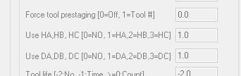
-
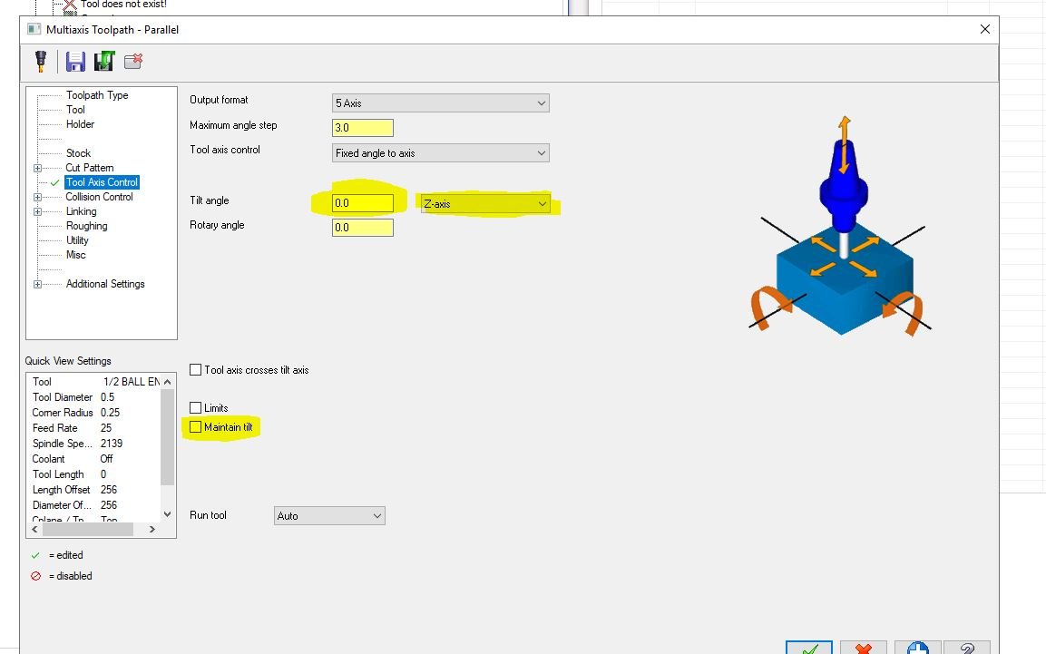
5 axis help! Wanting to lock out an axis from moving
huskermcdoogle replied to Silver3369's topic in Industrial Forum
Unless I am misunderstanding greatly here. As long as you have a dead simple pattern surface (centered on the c axis, probably spherical in this case), all you should need to do is use fixed angle to axis in the tool axis controls. Set the tilt angle and the axis to "tilt" about. If those don't work, use the maintain tilt checkbox, set conical limits, or possibly adjust your pattern surface. May ways to skin this cat. Now that I have read the post and possibly understood what is being asked.... I am guessing you have an issue with the pattern surface. Try using parallel instead of geodesic. Shouldn't make too much difference. Also, make a simpler pattern surface if you can and see if it does what you want, then introduce new variables as needed to get the output you want.