


Newbeeee™
-
Posts
3,425 -
Joined
-
Last visited
-
Days Won
40
Content Type
Profiles
Forums
Downloads
Store
eMastercam Wiki
Blogs
Gallery
Events
Posts posted by Newbeeee™
-
-
On 9/10/2021 at 2:39 PM, essid.mh said:
The proposed project is in the form of new mathematical models for calculating the tool path integrating the drive controller parameters as a boundary condition.
I'm 99% sure the old Yasnac Matsuuras had this....I bought a 1994 FX5 for a place I worked, and I'm sure we had the high speed tolerance codes where we specified "?" (can't remember now) and that was a 0.1mm profile tolerance, and another code for 0.05mm etc...
-
Can't remember the command now - simplify arc???
-
Kudos - it looks really good!
-
5 hours ago, Bill Craven said:
Back in 2015, we ran some tests in collaboration with Mastercam doing 75% dynamic stepover in X9 with a Sandvik 10mm 5 flute end mill.
The goal of this exercise was to see what could be accomplished with and older machine with limited memory and look ahead.
Machine = Haas VF5. CAT50 with a hydraulic chuck. (I don't think that it had a geared head. Spindle load was around 80% if I recall correctly.)
Material = 304ss
SFM = 265, rpm = 2550
Fz = .001, ipm = 12
Ae = 75%, (.28)
Ap = 200%, (.75)
It was run dry with high pressure air. The end mill measured 91 degrees F immediately after stopping

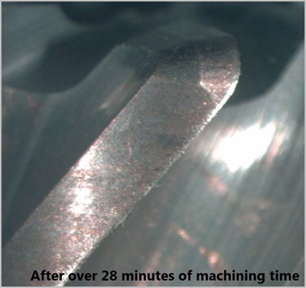
That has absolutely amazed me that the tool never snapped like a twig within 3 minutes!
And all testing i ever did comparing coolant to dry, was coolant lasted longer. And with facemill tips, when they started to go, if it was dry i'd better get there pronto! If wet, it was a long slow process where i could go and put the kettle on and have a brew! Then change the tips.
-
12 hours ago, JoshC said:
With a lot more work it could have been a really great tool but its still a pretty good tool for what it is.
Tool holder gauge line....(but I know that requires a full system re-write to do this).
Output to Excel and re-import would be nicer-errrr...!
-
Tom,
My figures for my old machines (which were budget Chevalier #40 10k spindle belt drive...) :-
12mm 5 flute (16mm "hammered" the part where the 12mm was softer and quieter and a whole lot better tool life)
Garr V5 gave best tool life for me with what i tried (being a pikey i never was too spendy on expensive cutters though )
)
304 (very similar to 316)
Short and stubby sidelock gave better tool life over a Schunk Hydraulic and a Showa Micron chuck
Coolant running at 10% also made a very noticeable difference (over 5%).
DOC 150%
Toolpath Rad 3mm
10% stepover (1.2mm)
S2555
F1500 (this gave a great tool life which is what I was after as we ran unmanned).
I wouldn't up the RPM that much - that is what killed the tools in 304. The feed can go up (a little), depending on rigidity of part/setup.
303 which is a totally different beast, we'd be running all day on very similar parts at S5000 F3000 and same 10% stepover and with 3x the tool life....

-
 1
1
-
-
On 9/3/2021 at 4:35 PM, crazy^millman said:
Crazy isn't it all the work put into a direction that only allows Milling tools to be supported.

When i jumped from X9 to 2020...i had hoped for a HUGE improvement in it.
Being honest....it's a bad college project....
-
Personally....I'd have a directory structure of
Customer
Within this a folder of Part No with Issue No
Within that folder everything to make the part including program and set sheet.
Also within, an OOI (Out of Issue) folder which has within that, previous Issue number together with all info to make the part at that issue (including copy of prog and set sheet). Prog to have at the top....Part # and Issue #. Set up sheet too.
Then...Cimco.
With the production prog in there and the set up sheet (pdf) linked to it. You can then pull the prog into a machine and if you make edits at the machine, send it back for approval by "someone" who can then delete it or save it overwriting the previous.
Nice and simple and excellent.
-
1
-
-
20 hours ago, JB7280 said:
That's pretty cool, but I'm surprised to see a Haas in a european shop!!
Lots in the UK too
-
-
1
-
-
I've always found that men are like wheelbarrows, and need to be pushed

Good luck Bob!
-
1
-
 1
1
-
-
57 minutes ago, Colin Gilchrist said:
[Your level must be between 1 and 2,147,483,647]
That 2147 blah blah number isn't cool for my OCD.
I think an enhancement request to round it down to 2000000000 is in order!
-
1
-
2
-
-
While y'all talking levels....the ability to freeze levels (to stop accidental move or deletion) would be excellent...(for those of us with fat sausage fingers
 )
)
-
3
-
-
Right click in ops manager
Select all and rename nc?
-
It'll be fubar'd by 2023....

-
2
-
-
5 hours ago, Bill Craven said:
I did the same thing.
When I was repairing CNC machines (which I did for twenty plus years), I attributed much of my success with being able to read (and re-read and re-read until I got it) the parameter manuals and ladder diagrams and other documentation.
Hahahaha - that's the yellow books for you!
Ffffaaaaarrrrrrr better now compared to the 90s, but read and read and read again until understandy!
-
1
-
-
28 minutes ago, Thad said:
24.5?


-
3
-
-
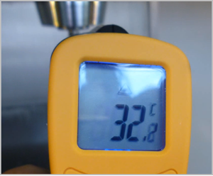
5 hours ago, mkd said:
...Speaking of thermal drift....

The AS machines are rock stable. But they're CY....
-
2
-
-
Being honest, you're using a basic 2axis lathe and 3axis mill.
So std fanuc posts will be 97% there for you.
I wouldn't bother about learning machine simulation etc at this stage or spend any time in configuring it. Gently gently catchee monkey. One thing at a time. As the guys have said, the videos are fantastic learning for the basics all the way to the advanced.
And the archive help here via searching, is also massive.
And yeh, Autodesk....!
-
5
-
-
There are a few makes and machine models that apply to what we're talking here, so it would need a regimented approach to dealing with each machine type (or model) "master configuration".
But I've had VMCs delivered at the same time - same make model and near sequential serial numbers which have had many parameter differences.
And i remember my old reseller (Hi Phil if you're reading) and him telling me of a couple of Integrex years ago. Customer received first machine and post issued.
Customer receives machine #2 and spindle (c) is opposite to machine #1. Rather than change machine parameter, customer requests a new post which is issued so each machine now has an individual post and certain jobs can only be run on #1 and certain others on #2.
What a ridiculous situation. But could be avoided with a "master configuration".
-
1
-
-
Colin - sweet call but would that not be better as an initial "set up" program?
Surely the "important" machine parameters (specific model or machine series) can be decided upon (ie the functioning ones to check and not ones such as how pressing reset is configured etc) between the MTB and CNC, then a "master" set of those parameters can be run when installing Mastercam MTM?
So there's a master post (Mcam) and master parameters (MTB) that are supplied together?
I guess it's just an automation way of what James does when he goes into a company and configures the MAMs - but CNC will obviously always be on the backfoot if the machine is not configured as they expect.
Same as Bob is on the backfoot because the post isn't outputting MCodes where the machine needs them...
-
1
-
-
1 hour ago, gcode said:
Remember the Mars probe that vanished as it fired it's rockets to go into orbit around Mars about 25 years ago
After much investigation, the cause was discovered.
It had a metric navigation system, and the NASA engineer who wrote the orbital entry program
delivered the code in English. They found the wreckage 20 years later a couple of thousand miles off course.
Maybe something similar is going on here.
Sensors that read Fahrenheit and parameters set in Centigrade would account for the large amount of thermal
comp happening here.
777 had something similar...first fully CAD aircraft and the wire looms for the tail were outsourced to Germany (who worked in metric).
When they were delivered for the first (5?) builds, they were many feet short (and not very stretchy
 ).
).
Metric. Inch. I dunno the prob. It's just a 24.5 conversion....
-
3
-
-
4 hours ago, JParis said:
This may not be relevant but I'll offer it up...
On our newer Mazaks, we have experienced a similar growth issue.....after much back & forth we found it was the thermal compensation....it was set too high and was causing corrections that were causing problems.
Don't know if something like that might be happening
...and I guess that the placement of said sensors, and how they're actually bonded to the iron, makes a HUGE difference too?
-
Bob
If the machine from just sitting powered shifts 2 thou centreline of spindle bore, it has a HUGE fundamemtal instability problem.
What is your tailstock/sub spindle like? Does the machine turn parallel day to day?
...and i would look through the books and confirm the parameter numbers and check for my own sanity...

New CAM programming algorithms
in Post Processor Development Forum
Posted
....and a bit more trolling ....purely because you state "Industry 4.0" (which for those that don't know, is the WEF's 4th Industrial revolution)
Below is your post on Practical Machinist, stating you already have the algorithm to allow for optimal tolerance blah blah (attached).
So how does this work - how does your algorithm "tell the CAM" to allow for the following different machines?
Can you please explain?
I want to make the same part on 3x different machines.
#1 machine is a large Haas VF8 machine - a big heavy table with slow acceleration and deceleration.
#2 machine is a much smaller Haas - smaller lighter table with the next generation faster processing control and much better acc/dec.
#3 machine is a gantry design machine - the table is fixed and the axes are a bridge/portal design. So although mass of component on the table is irrelevant, unfortunately I have an issue with the X axis where there is "some" out of squareness to the Y.
This has an early Fanuc control with no lookahead processing.
???