


djstedman
-
Posts
577 -
Joined
-
Last visited
Content Type
Profiles
Forums
Downloads
Store
eMastercam Wiki
Blogs
Gallery
Events
Everything posted by djstedman
-
Oh also.. along the same lines as what Hockey guy said.. you can always touch off another tool then use an indicator in a mag base on the table to find the difference between it and the small tool then plug in your offset
-
If your setting something that small. . a good method is a dowel pin of a known size on top of a 2 inch block.. Check to see if it stops rather than rolling under .. if it does move up .0001 and try again.. since its rolling its putting out almost no force on the small endmill..
-
How best to toolpath a feature like this?
djstedman replied to djstedman's topic in Industrial Forum
Mr.Fish .. that path looks great for finishing with a ball which i'm likely going to have to do Crazy .. That Multisurface path is awesome.. would never have thought of doing it like that .. Damn.. that's some great stuff from both of you .. definitely has got me going in the right direction.. Cant thank you enough for pointing me in the right direction! -
How best to toolpath a feature like this?
djstedman replied to djstedman's topic in Industrial Forum
For the roughing after seeing people mention a pocketing path with axis sub, it made me think a bit and I have been messing around with making a dynamic mill path using axis sub and that looks like it might work pretty darned good As for the finishing, when I tried any of the multiaxis paths my biggest problems came from it wanting to dive right through the part and it seemingly wanting to ignore check surfaces.. Then again I have never been able to get my mind wrapped around that collision strategies page having 4 options.. and to say the documentation for that stuff is weak is being kind of generous.. cant wait to see what you come up with. -
Best bet is to draw the tool at the actual diameter it will be and not bother having it try and scale the tool.. although its supposed to be possible I know I have found the best luck with drawing the tool at 1:1 and using it like that. Its easier to draw and most times custom tools will only ever be one size anyhow.
-
How best to toolpath a feature like this?
djstedman replied to djstedman's topic in Industrial Forum
Yeah I should have thought to attach the file itself and not just a picture, anyhow here is the file.. I removed the toolpaths I had in there that I was testing with because they weren't even close to working.. EXAMPLE_SCALLOP.MCX-7 -
How best to toolpath a feature like this?
djstedman replied to djstedman's topic in Industrial Forum
I appreciate the input so thanks for that everyone, I was really looking for some more insight into the multiaxis paths though since I know I should be able to use the multiaxis paths to create a 4 axis solution for this. I know there are some 4 and 5 axis guys on this forum that could probably at least point me in the right direction.. I was messing around with parallel to surfaces and was soooo close .. but yet so far away.. Assuming I was dead set on a multi-axis path locked to 4-axis.. which would seem to be the best strategy for this type of a feature? -
How best to toolpath a feature like this?
djstedman replied to djstedman's topic in Industrial Forum
Well on the actual parts the rad is 10MM the walls are perpendicular though they do have a weird runout radius in the ends .. its gonna have to be a rough then finish later job no matter what.. Its being done in 300M steel (pretty much a fancy 4340 through hardening steel) Anyhow.. its going to be roughed then brought up to about 55HRC then it needs to be finished at hardness its the only way to maintain our tolerances The pocket idea and axis sub might be a good way to go for roughing the majority of it though.. gonna have to attempt that.. Still looking for a nice smooth method for finishing since the plan is to profile the majority of these things with ballmills made for hard milling.. -
From what I heard from other posts here that is not able to be edited based on a decision made by CNC software.. It has something to do with that field possibly being used internally inside of MC based on different things they may do with different tool manufacturers .. since MC uses that designation for different things it would cause a conflict if everyone were able to use it possibly breaking stuff .. Personally I think they should have made a user modifiable field for manufacturer and kept that particular one hidden .. but from what I have gathered that's the reason for it being uneditable
-
How best to toolpath a feature like this?
djstedman replied to djstedman's topic in Industrial Forum
Ok Ok .. hitting attach helps .. it should be there now lol -
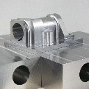
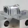
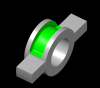
OK I have a part that is configured pretty much like what I am posting a pic of below, I can't share the actual part since its from a customer but suffice it to say it has a ton of scallops on it that look pretty much like what is shown below in green.. although the actual part is much longer so it wouldn't be possible to sidemill these scallops If there were just one feature like this I might muddle through by creating geometry and doing a lot of manual coding, however since there are a lot of features I was hoping to maybe use a multi axis path powered by surfaces / solids.. I plan on doing these pockets as well as a bunch of other features with the part setup on a 4 Axis VMC, It seems to me this should be possible using multiaxis paths and restricting to 4 axis, but so far I have been sitting here cursing the part, my computer, and my inability to get it to make a decent path.. FYI I have MCX7 that I am using for this.. So .. any suggestions?
-
It depends on what i'm doing and cutter diameter, depth of cut etc.. , but in general In a dynamic mill in steel I'm generally cutting around 200+IPM with backfeed set to 1000IPM, in Aluminum I'm pushing more have been as high as 500IPM with the cutting with the backfeed around the same.. 1000IPM
-
guess I have been lucky but on our machines with no parameters tweaked at all the g61.1 option runs very smooth up to as high of feedrates as I have found our tools capable of handling..
-
I think this only will work if you have the option MAZACC3D, I believe its Mazak's 3D High Speed Smoothing Option I know if I try and use it I get an alarm.. however I do use G61.1 to enable feeding over 315IPM For what I have done using our newer Mazak's using G61.1 is enough to hold pretty fussy 3d profiles without having that option. If your going to enable high backfeeds (critically important to reduce cycle times) and or feedrates over 315IPM then you will need definitely need to use G61.1 Im interested to see what others have to say about this though..
-
I track tooling through an access database. We keep our tooling in a locked Lista cabinet which has the drawers arranged so each different type of tool has its own location. Only designated people have keys to the tooling cabinet. When a setup / operator needs tools they see one of the guys with a key.. this minimizes unnecessary tool replacement, hoarding etc. Also this way people don't run the cabinet out of tooling without anyone that can order more knowing about it. Drawers are labeled by letter and each location within the drawer designated by number. Based on this Tools are assigned a location like A-10, B-22 etc.. Since all the tools are in an access database which includes all the information about each tool like Manufacturer, Tool type, EDP#, Diameter, Overall Length, Flute Length, Radius, Location, etc., etc. its easy to create a report which lists all End Mills, Bull Mills, Ball Mills etc.. Additionally I have another report which lists all tools by location. About once a week I print out the report which lists all tools by location and then go through the drawers of the cabinet and note what tooling needs to be restocked.. then I just order whats needed to maintain stock on those items. Its not perfect but it works pretty well for our needs and allows me to manage all our tooling needs with very limited time expended on it .. currently we stock around 300 different types of tools using this method and we have reduced delays in getting jobs running and red charges for shipping. We also have our high volume tools in autocribs which are stocked on consignement by our main tool supplier.. however to be honest I prefer having them in our cabinet since we tend to have more stock outs in the autocribs than in our cabinet using the method outlined above.
-
No .. you can still use an arc value.. just make the line in and line out perpendicular.. and all values need to be at least 50% of the cutter to account for that in your lead in / lead out Arc sweep can be whatever you want it to be as well .. You can modify things to see how they work by watching in backplot As for threadmilling I never use mastercam for it.. I use code generated by Vardex TMGen program since it has better ability to adjust feedrates on lead in lead out
-
Im pretty sure you would have already thought of this.. but if its possible to get to it with a saw cutter getting a 1mm full radius saw would probably save a ton of time on this..
-
Have you checked and verified the angle of the tool is correct using an optical comparator or something? Most likely the tool is not ground to the exact angle you think it is.. if the angle of the tool isn't correct (ie matching your contour angle) you will get a step..
-
Renishaw Calibration Probe Macro
djstedman replied to cncchipmaker's topic in Machining, Tools, Cutting & Probing
People are just saying that why would you want to re-invent the wheel when someone already has the market cornered on them. You have to determine what you need to actually do, ie define your problem in geometric terms. Next you have to apply the mathematics/geometry that is necessary to implement solutions to the problem you defined in step 1 Finally and last of all you need to take everything you figured out in steps 1 and 2 and go through the relatively simple step (compared to the first 2) of coding the macro. As to your last comment about not getting much help, If you ask me your lack of specific help up to this point is due to how you asked your question and not what the question is about.. If you want help then ask a specific pointed question and make sure to provide enough background information that the person attempting to answer your question has enough information to do so. Your initial question and your subsequent replies didn't provide enough details and left me (and I imagine everyone else in the thread) having to make assumptions about what exactly you were trying to do and why you were trying to do it, additionally it gave the distinct impression that you had no idea of the complexity of the project you were about to attempt, and finally it gave the impression that although you would like everyone to take their time to help you out you couldn't be bothered to take the time yourself to post a well thought out question with enough detail that someone could actually help.. If you couldn't put the time and effort into the question.. why should someone else jump through hoops to answer.. -
CT (New England: MA, CT, RI) - Mastercam User Group
djstedman replied to scooke4073's topic in Industrial Forum
Im in northwestern CT.. and I am interested depending on times and whats going on .. I definitely think K2csq7 should buy us all lunch though .. lol.. -
Tool list chronologically in order
djstedman replied to qstix's topic in Post Processor Development Forum
When I did this I was using mpmaster, those buffers were being used.. I ended up using your code for a starting point .. anyways I got it working and doing what I wanted .. thanks for the update though -
change this postblock as well psub_st_m$ #Header in main level result = nwadrs(strn, main_prg_no$) (and just realized someone tricked me into adding to a post that's 6 months old.. i'm betting this was already resolved)
-
If you bought an insertable one .. although that insert would only make 12TPI holes.. for any other TPI you just buy different inserts and re-use the body. A single point tool is more likely to wear that one point much faster than a multi flute insertable threadmill and for holes of this size its really not going to take too many holes single pointing to waste so much time you could have bought the insertable threadmill and the proper inserts and knocked them out faster freeing the machine up for other work. Those are probably the reasons that its hard to find a tool for what you are looking for, that said.. if your dead set on making it single point.. you could always look for a insertable body and then alter the inserts and remove all but the bottom tooth.
-
I am using X7 and mostly think its good, that said If you rely on STL driven paths I highly recommend you read what other people are saying about the troubling issues with STL files in X7 over in the following topic.. When I attempted to try using STL models to drive rest rough paths the huge STL filesizes X7 generates were killing my system which is an i7 with 32Gb of ram.. http://www.emasterca...showtopic=74372
-
Reaming Hardened Steel at 55Hrc
djstedman replied to djstedman's topic in Machining, Tools, Cutting & Probing
OK so I kind of fibbed a bit .. its not actually 4340 .. its really 300M .. but 300M is pretty much the same composition as 4340 with a couple added ingredients.. but most people look at me funny when I say 300M so I just said 4340 since everyone knows what that is.. Anyhow.. the material is certified material provided by the customer and hardness is between 53-55 Hrc certified and checked at incoming inspection into our facility. I have been doing some testing today and I think im getting somewhere.. hopefully will get this sorted out on Monday..

