


djstedman
-
Posts
577 -
Joined
-
Last visited
Content Type
Profiles
Forums
Downloads
Store
eMastercam Wiki
Blogs
Gallery
Events
Everything posted by djstedman
-
gcode, I could be wrong but it sounds like if you edit the file CamMan is talking about.. that is the default settings for verify .. so then they would likely stick.. Of course save a copy first .. but worth a shot..
-
Multiaxis cutter compensation
djstedman replied to AlbertZini's topic in Post Processor Development Forum
This wouldnt solve your initial question for how to do this in a post.. but just a thought.. maybe if it is only x values you could use macro variables for the given positions in X and have them set at the beginning of the program.. then you effectively make your own comp in the X axis without ever actually turning comp on.. Just a thought and might not work for your situation.. just figured I would throw the idea out there in case it helped you.. -
Ok, so I wanted to modify how some of the manual entry stuff worked in the MPMaster based post that I have.. I am no expert at post mods but I beat on it until its doing what I wanted.. so I figured I would post what I did on the off chance maybe it might help someone else and also so I could maybe get some pointers on if there might have been a better way to accomplish my objectives... This is my first time doing a mod of a post that was this complicated on my own.. so although it seems to work ok.. im still curious to know if there might have been a better way and or if people think this is cool or what.. I was pretty thrilled to get this working.. Anyhow.. first .. to explain what was going on and what i wanted to happen.. So I basically have the MCX7 file setup so that I have a manual entry as comment This contains setup information.. etc .. ie location of zeros / comments about setup Then I have a manual entry as code .. this contains a probing cycle for this op.. this is fairly common for us since we do a lot of parts where we probe for location So with that as my setup in my MCX file I was getting the following.. which was all out of order.. O208010 (12345F10_ORIG) (X0 - LEFT EDGE OF BLANK) (Y0 - REAR EDGE OF BLANK) (Z0 - TOP OF BLANK MINUS .005) (NOTE- PART MUST BE DOVETAILED TO FIT JAWS) M01 (PROBE XYZ) T23 M6 G0G90G54X.25Y-.25 G0G43H23Z3. G65P9810Z.25F60. G65P9811Z.01S1 G65P9810X-.3Y-.25F60. G65P9810Z-.25 G65P9811X0.0S1 G65P9810Z.25 G65P9810X.25Y.25 G65P9810Z-.25 G65P9811Y0.0S1 G0G91G28Z0 G0G91G28Y0 M01 (MILL) (MACHINE GROUP-1) (MCX FILE - M:\12345F10.MCX-7) (PROGRAM - 12345F10.NC) (DATE - MAY-13-2013) (TIME - 1:10 PM) (T2 - 2 INCH FACEMILL W/.031 RAD - H2 - D2 - D2.0000" - R0.0310") (T13 - 1/2 3FLT ALU-POWER 2. LOC - H13 - D13 - D0.5000") (T11 - 1/2 2FLT BALL - H11 - D11 - D0.5000" - R0.2500") (T9 - 1/4 4FLT W/.06 RAD - MILL CABINET E-24 - H9 - D9 - D0.2500" - R0.0600") (T4 - 1/8 4FLT BALL - MILLCRIB BIN42 - .8 EXT MIN - H4 - D4 - D0.1250" - R0.0625") (T8 - 3/8 4FLT W/.125 RAD - MILL CABINET D-22 - H8 - D8 - D0.3750" - R0.1250") (T6 - 3/8 X 90 4FLT CHAMFER MILL - H6 - D6 - D0.3750") (T30 - 120 DEG SPOT FOR TIMING MARK - H30 - D30 - D0.2000") G0G17G20G40G80G90 G91G28Z0. G28Y0. (FACE TOP OF PART .005 OVER) (COMPENSATION TYPE - COMPUTER) (2 INCH FACEMILL W/.031 RAD) T2 M6 What I ended up with once I completed my mods was the following .. which to me at least seems a lot more useful.. O208010 (12345F10) (SAVE 12345F10.NC) (DATE - MAY-13-2013) (TIME - 11:32 AM) (MCX FILE - M:\12345F10.MCX-7) (T2 - 2 INCH FACEMILL W/.031 RAD - R0.0310") (T13 - 1/2 3FLT ALU-POWER 2. LOC) (T11 - 1/2 2FLT BALL - R0.2500") (T9 - 1/4 4FLT W/.06 RAD - MILL CABINET E-24 - R0.0600") (T4 - 1/8 4FLT BALL - MILLCRIB BIN42 - .8 EXT MIN - R0.0625") (T8 - 3/8 4FLT W/.125 RAD - MILL CABINET D-22 - R0.1250") (T6 - 3/8 X 90 4FLT CHAMFER MILL) (T30 - 120 DEG SPOT FOR TIMING MARK) (X0 - LEFT EDGE OF BLANK) (Y0 - REAR EDGE OF BLANK) (Z0 - TOP OF BLANK MINUS .005) (NOTE- PART MUST BE DOVETAILED TO FIT JAWS) G0G17G20G40G80G90 G91G28Z0. G28Y0. M01 (PROBE XYZ) T23 M6 G0G90G54X.25Y-.25 G0G43H23Z3. G65P9810Z.25F60. G65P9811Z.01S1 G65P9810X-.3Y-.25F60. G65P9810Z-.25 G65P9811X0.0S1 G65P9810Z.25 G65P9810X.25Y.25 G65P9810Z-.25 G65P9811Y0.0S1 G0G91G28Z0 G0G91G28Y0 M01 (FACE TOP OF PART .005 OVER) (COMPENSATION TYPE - COMPUTER) (2 INCH FACEMILL W/.031 RAD) T2 M6 Anyhow .. first I added the following in the variables section... ## variables to trap comments insanity : 50 sop_comc : "" sop_comt : "" ## string buffer to handle manual entry str_man_ent : "" rc1 : 1 wc1 : 1 size1 : 0 fbuf 1 0 80 0 1 ## string buffer to handle manual entry str_man_ent2 : "" rc2 : 1 wc2 : 1 size2 : 0 fbuf 2 0 80 0 1 Then I modified pheader2 to look like ## if not in start of file... post man ent as comment as usual.. if sof = zero & gcode$ = 1005, n$, pspc, scomm_str, scomm$, scomm_end, e$ ## if in start of file.. buffer man ent as comment to be output where we want.. if sof & gcode$ = 1005, [ sop_comt = scomm$ str_man_ent2 = sop_comt str_man_ent2 = wbuf(2, wc2) ] ## if after start of file post man entry as code as usual if sof = zero & gcode$ = 1006, n$, pspc, scomm$, e$ ## if before start of file buffer man entry as code to be output where we want.. if sof & gcode$= 1006, [ ## save scomm to sop_comc sop_comc = scomm$ str_man_ent = sop_comc str_man_ent = wbuf(1, wc1) ] I also modified this line.. if gcode$ = 1008 & header = zero, n$, pspc, scomm_str, scomm$, scomm_end, e$ to look like this to supress output of the operation comment till after header and sof ## op comment only after start of file if gcode$ = 1008 & header = zero & sof = zero, n$, pspc, scomm_str, scomm$, scomm_end, e$ Finally I modified psof to look as follows.. psof$ #Start of file for non-zero tool number ## init our man entry buffer pinitbuf1 ptravel pwritbuf5 pcuttype toolchng = one if ntools$ = one, [ #skip single tool outputs, stagetool must be on #stagetool = m_one !next_tool$ ] tooltotal = rbuf(4,0) #Reads total tool and null tool changes if toolcountn <= tooltotal, nexttool = rbuf(4,toolcountn) else, nexttool = first_tool$ if tool_table = 2, ppredstck if tool_table = 3, pmetastck spaces$=0 if output_z = yes$ & tcnt > 1, [ scomm_str, "OVERALL MAX - ", *z_tmax, scomm_end, e$ scomm_str, "OVERALL MIN - ", *z_tmin, scomm_end, e$ ] spaces$=sav_spc ## dump comments to pcomment / pcomment2 comment$ ## moved this here from pheader ## added this section to read from buffer 2 and post to NC file ## if theres comments as text post them before the ## cancel codes if sop_comt <> sblank, [ insanity = 0 while insanity < wc2 - 1, [ sop_comt = rbuf(2,rc2) n$, pspc, scomm_str, sop_comt, scomm_end, e$ insanity = insanity + 1 ] ] if plane$ < 0 | opcode$ = 3 | opcode$ = 16, plane$ = 0 pbld, n$, *sgcode, *sgplane, *smetric, "G40", "G80", *sgabsinc, e$ sav_absinc = absinc$ absinc$ = one if wcstype <= one, #Work coordinate system [ pfbld, n$, sgabsinc, *sg28, "Z0.", e$ pfbld, n$, *sg28, "X0.", "Y0.", e$ pfbld, n$, "G92", *xh$, *yh$, *zh$, e$ ] else, [ pbld, n$, sgabsinc, *sg28, "Z0.", e$ pbld, n$, sgabsinc, *sg28, "Y0.", e$ ] absinc$ = sav_absinc sav_mi9 = mi9$ sav_workofs = workofs$ if sav_workofs < 0, sav_workofs = 0 ## Added this section to read from buffer 1 and post to NC file ## output string saved operation comment as code ## sop_comc here since cancel codes have been written ## if sop_comc <> sblank, n$, pspc, sop_comc, e$ if sop_comc <> sblank, [ insanity = 0 while insanity < wc1 - 1, [ sop_comc = rbuf(1,rc1) n$, pspc, sop_comc, e$ insanity = insanity + 1 ] ] ptlchg_com sof = 0 And the last thing I did was remove $comment from pheader when I moved it to the psof block as shown above.. I also made a few other minor alterations to accomplish some other more mundane things like altering how toolchanges were formatted and swapping the MCX line location and changing the program name line to say (save filename.nc) rather than program name - .. but these were pretty simple tweaks in comparison to moving the manual entries around..
-
Ok well Aaron posted while I was typing my last post, but from the sounds of it, it seems like there is a learning curve to X7.. because thinking about it.. using stock model and stock model compare allows me to see the cutting conditions and apparantly saving the STL too. (Thanks for pointing that out Aaron) So I guess now I can think of verify of more of a tool for checking for collisions and stock model for checking blends etc.. and verify less as a way to check my blends etc..
-
Yeah I had also noticed that the STL files were definitly bigger .. I wasnt sure on the accuracy part of them though.. I have to say the overall quality of the verify is not impressing me much.. its great thats its in its own window but verify is pretty much at the core of what I do as a programmer, I constantly rely on it for how blends will look etc.. it doesn't do me much good to have it be able to run a verify on a huge part or have it in its own window, if the end result doesn't give me the information I need. Maybe I just need to get used to it.. but that screenshot of a flat endmill cut and the graphical errors that show up does a great job of illuminating the issue. The STL file issue to me seems less important since if you use stock models and work using views + multiple machine / toolpath groups you can process the entire part in one file.. although with the same issue as STL files.. once the file gets too big this method breaks down as well.. At least with the STL files I can use Meshlab to shrink the files down some..
-
Yeah all mine too .. so would probably cause an e-stop alarm .. there are machines with that many tools though so was trying to get more info..
-
I assume you mean emergency stop? Did the machine crash or simply alarm out? Is the tool using height offset 317? Does the machine have 317 height offsets?
-
In my experience if the person in charge doesn't have the ability to recognize and solve problems on the floor then thier people / leadship skills will most likely not help much. If they are willing to listen to the people with the technical skills that helps, but only if they can recognize what information is in fact reliable and worth acting on and what information is not. Often a person without the requisite skills will not listen to a skilled employee because they don't recognize the value of the ideas being brought forth, or they don't have the nerve to risk implementing changes that may require a costly investment. As an example, I have seen in the past where a supervisor allowed much of the tooling in the shop to decline in quality to save money, his replacement came in and spent a lot on quality tooling (mostly to replace things the previous supervisor would not) and we saw overall quality and on time delivery went through the roof while scrap percentages plummeted. The first guy couldn't recognize that sometimes saving money up front costs you more in the long term, the second guy came in, realized the problem and made the call to do something about it. People skills are great but in a Machining environment its critical that the supervisor can have the technical proficiency to be able to recognize problems and address them and be able to understand how that effects the skilled guys on the shop floor.
-
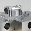
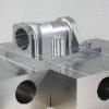
Just a question.. does the STL file look like the picture you posted? Since the pic is from within Verify I was wondering if the actual STL file that was output was any better quality
-
lmao.. so should we consider this thread officially hijacked by high speed machining videos now? lol and btw.. I will take two of those horizontals.. j/k but damn thats fast..
-
Yeah, that worked.. In fact he posted it without changing anything to show me how it wouldnt work .. and it worked .. he actually had the views for everything setup correctly but since his posts didnt work in the past .. about 2 years ago in X3 or X4 .. he just assumed the newer posts we had wouldnt work and had never tried it.. im gonna go strangle him now.. lol Thanks for the help.. at least it made me force him to try it and got the facts out in the open.. and better still I solved my problem without doing any extra work ..
-
In the new Verify window .. under the file menu.. is a menu item called options. By changing the 'save STL tolerance' you can make the quality of the STL more precise.
-
Yeah we are using a modified MPMaster post.. so I will let him know what you suggest and see if it works for him.. Thanks for the input.
-
OK, lets see if I can explain my situation.. lol One of our programmers creates his programs so that all of his operations are in one file and use different views based on the different operations, he does it this way so he can use one file to make a complete part and have the last operation create the stock for the next. Since we are moving to X7 soon I have been asked to get our posts upgraded / sorted out for X7 .. and this is really not a problem, however because of the way he posts out his code.. the post sees his non rotary operations as rotary operations since they are assigned to views other than the standard top view. In the past he has used two posts, one thats setup for only 3 axis output and wont post A Zero moves regardless what view its used in, he uses this on the non-rotary operations, and a 4 Axis post that he uses for any actual rotary operations so he gets the rotational indexing as reqd. For the record, the 4th Axis post does supress output for non rotary operations if they are in the top view, however its posting A0 moves on toolchanges which is no good since we typically run the non rotary operations in our machines without rotaries which means the A0 calls trip an alarm. Since im upgrading posts I was thinking it would be nice to not have to recreate / update / maintain basically twice as many posts just so he can have three axis posts to supress rotary output. I had considered using a Misc Int to supress the rotary output but didn't want the programmer to put it into every non rotary op. I was also wondering if it might be possible to supress it based on view name (if view name is able to be gotten from the NCI ugh) Maybe jsut having a 3 and a 4 axis post is the best option.. anyhow.. im just looking for suggestions since I know there are plenty of people here that are far better with posts than I am. Any suggestions / help you can provide would be greatly appreciated ..
-
If you convert a library to text you get the following.. gives tooltype id's as well as some other stuff, I would assume the tool type id's would be the same for compatibility reasons.. so hopefully this helps.. I reformatted it so it made sense as a post in here btw.. # (tool types) # CENTER DRILL 1 # SPOT DRILL 2 # DRILL 3 # TAP-RH 4 # TAP-LH 5 # REAMER 6 # BORING BAR 7 # COUNTER BORE 8 # COUNTER SINK 9 # END MILL FLAT 10 # END MILL SPHER 11 # CHAMFER MILL 12 # FACE MILL 13 # SLOT MILL 14 # CORNER RAD MILL 15 # DOVETAIL MILL 16 # TAPER MILL 17 # LOLLIPOP MILL 18 # END MILL BULL 19 # BLOCK DRILL 20 # ENGRAVE TOOL 21 # BRADPT DRILL 22 (tool capabilities) ROUGH & FINISH 0 ROUGH 1 FINISH 2 (tool corner radius) NONE 0 CORNER 1 FULL 2 (coolant types) OFF 0 FLOOD 1 MIST 2 TOOL 3 (spindle direction) CW 0 CCW 1 (canned cycles) SIMPLE DRILL 0 PECK DRILL 1 CHIP DRILL 2 TAP 3 BORE1 4 BORE2 5 MISC1 6 MISC2 7
- 1 reply
-
- 1
-

-
Well I just tried it.. I still dont get randomly appearing toolpaths.. but I can confirm that 'repaint toolpath' does indeed get checked to on as soon as you toggle the stock model on and off This actually seems to happen no matter what toolpath you choose.. when you hit 'toggle display on selected operations' button the 'repaint toolpath' checkbox in the config goes back to being checked. On my system this doesnt seem to make any difference.. but it still doesnt explain why on yours with only one operation selected you get a bunch of other toolpaths randomly displaying.. that still doesn't happen for me..
-
Yeah I can see it.. its really weird.. and it doesn't do anything like that on my system.. I even tried making a stock model and then regen and then toggle without selecting any other toolpath.. I know I use openGL and have hardware acceleration turned off for video settings .. I know in the past with a different system having hardware acceleration turned on in the config caused some bizaree stuff to happen. Maybe try that to rule it out..??
-
This is really bizarre .. I just tried it in X6 MU2 and I cannot replicate it.. im wondering if its possible it isnt a problem in mu2 .. that would be odd though since supposedly mu3 was mainly for translators and things
-
Might seem like a unrelated question, but whats your graphics card, and do you have the best drivers for it.. Is there another computer you can try to check if it happens on that as well? Cause this doesn't happen on my machine.. Not sure if its a setting or a graphics issue, but yeah I can toggle the stock model on and off without it changing all the other toolpaths.
-
Have you tried selecting the rest of them, other than the stock model and toggling them off.. dont think you should have too .. but if you do do they go off and the stock model stay on? If you dont have the stock model in there does it work correctly when the stock model isnt in the mix?
-
For two peices I might .. would be easier than going through all the trouble to make a good solution to drop the slug.. if you have something like a feedmill or something that could be chewed through pretty quickly.. problem is once you get to the bottom it still sucks breaking through.. then again if I were to do it here I would totally cheat .. drill a hole in it and make the wire guy cut the slug out then I wouldnt have to worry about it .. lol
-
I think if you actually let the center drop your going to end up wrecking cutters when you get to the end of your peel mill.. when that thing is hanging by a thread its going to push off and your gonna ruin tool life.. I would make a fixture with some clamps around the outside and a couple 1/2-13 tapped holes somewhere under the drop.. then you can pop some holes into the plate and then bolt it down so the drop doesn't move while you cut it, that will be a lot nicer to the tool .. also need to make sure theres plenty of room for the huge pile of chips your going to make to go. I am assuming your thinking of a 5 flute 3/4 cutter going one shot through.. so thats what the following is based on I haven't done tons of titanium either but that feedrate sounds pretty extreme the 400 sfm is prob ok since its a peel mill but an .008 chip load at 2x dia is kind of asking a lot.. you might be able to do it though.. I would probably start somewhere like 60IPM (.006 chipload) and then push it more if it seems like it could take it.. I would probably be taking at least .05 to .075 stepover though .025 is only like 3.3 percent of the cutter and is going to mean being in the cut a LOT longer and therefore getting less out of one cutter .. I generally would be taking at least 10% of the cutter but since its titanium maybe I would start off at like 6 or 7 percent to be safe.. but you could prob get away with 10 percent and possibly more. And btw .. if you have to do a lot of them buy a high end holder that minimizes your runout since it will greatly increase tool life.
-
Windows 7 or 8 for long term compatibility
djstedman replied to Kevin Kostiuk's topic in Industrial Forum
Dont trust Microsoft.. its all a ploy to get you to buy winblows 8 so that they can remove it again in the next update and have you stuck with it .. I have seen in some tech news articles that they pretty much have been saying if people dont like windows 8 its to bad cause they wont bother changing for thier users.. Hard to beleive the arrogance from them.. -
I agree that right now two ops is prob the simplest way to do it.. Wouldnt it be great if you could assign a roughing and finishing speed and feed to a tool Then have a contour toolpath that would do a rough and finish that actually used those values and had boxes for stock to leave on wall rough stock to leave on floors rough stock to leave on walls finish stock to leave on floors finish That would save me a ton of time on a lot of my toolpaths and keep me from CONSTANTLY opening and closing windows to change feedrates on finish passes.. We can only hope that this becomes a reality someday ..
-
I haven't ever been able to do it in one operation, what I usually do is make two identical ops.. and have the first one leave .002 on walls and .002 on floors, and the second one cuts finish this also lets me alter RPM and feed independently depending on whether its a rough or finish op. I dont beelive using this method there is any 'safe' way to force it to keep the tool down.