David Colin
-
Posts
791 -
Joined
-
Last visited
-
Days Won
10
Content Type
Profiles
Forums
Downloads
Store
eMastercam Wiki
Blogs
Gallery
Events
Everything posted by David Colin
-
I just opened your file and in your application, your Cplane should be set to TOP (= your Tplane). Then you'll see 3D contour type will be selected (or selectable). BTW, i don't remember using a Cplane not equal to Tplane... so 99% time it will be set like that.
-
<Deleted Links>
-
If 3D option is grayed that means your geometry is located on the same plane as your machining plane (it looks like you drew on front plane on your picture1). On your picture2, there is a tab named 'plane'. There, you ll need to set your Tplane correctly: it should be left plane if i understood well... After that, perhaps you will need to exit this window clicking OK button then re-open toolpath parameters window to be able to change toolpath type from 2D to 3D
-
Yes I read this help file recently and I tried to make a tool like that and I remember I couldn't get it work...
-
As Colin explained, after trimming, you still can see (and even alter) original nodes clicking a button in 'Analyse entity' window. Note that in 2017, there is a new information field in 'analyse entity' window which indicates trimming factor of splines.
-
You can do that with 2D contour substitution, rolldie chook or some multiaxis toolpaths. A file shared would help.
-
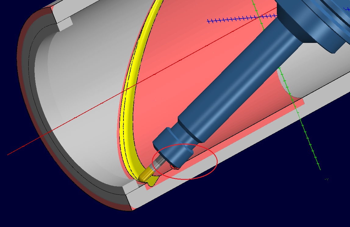
There are 3 problems with your geometry: - There is a tiny gap in your chain - Overall tool is not correctly located. It should be in 'upper-right' side of top wcs (X+/Y+). However, you still can move it below Y-axis if you need to control your tool a special way (not at tool tip) - Tool center line should'nt be drawn or you need to draw it with a dash style Here is the corrected file CUSTOM TOOL TEST-MOD.mcx-9
-
adding tool mfg's to drop down in tool descriptor
David Colin replied to BenzB's topic in Industrial Forum
With other applications it can go even further like automatically filter holders according to tool shank diameter. One thing, very easy to implement that would make holders selection easier in my workflow would be to be able to link an holders library for each machine (in machine definition). Then all operations would load this one and would show you spindle compatible holders only. Another way could be to add a spindle interface field in machine definition (cat40/capto6/...), mix all holders in a library and Mastercam would be able to filter automatically. Would be great improvements not so difficult to implement... -
Mori NH-5000 tool life management question
David Colin replied to Slixmix's topic in Industrial Forum
Our NH5000 has 120 tools here and with TLM we are still using G43 H99 -
This is really a great job! That new fixture library is awesome and should already be native in Mastercam...thank you!
-
Backplot time is not really reliable. I usually have issues as i'm using compensation in control...
-
Helix is pretty big so i m not sure a bigger cutter can do it better.I ll try it. And yes I like this toolpath too ☺powerful, versatile with a lot of control. (Et je préférerais pouvoir écrire en francais
-
Here is a toolpath example on part designed by Ron. Can't really be machined like that though but perhaps it will help. https://www.dropbox.com/s/2dkrvejuceqkin5/5th%20Axis%20Knurl.mcx-9?dl=0
-
adding tool mfg's to drop down in tool descriptor
David Colin replied to BenzB's topic in Industrial Forum
Yes this will be in 2017 release. Tools grades will be customizable the same too. -
I guess Camware and Mazacam can do that.
-
Vericut interface is creating its own tool library inside from Mastercam one. That works for mill and lathe tools and i suppose it should work the same with MT (i didn't see it)
-
I program 1 Mazak integrex200ST(with lower turret/Fanuc640MTpro control) and 1 Mazak integrex200-IVS(Matrix control). I program main features (part transfer, machining on both spindles with any turret, multiaxis toolpaths) both with Mastercam 'lathe' without any problem but i have tweaked posts my reseller provided for several months (years?) to make them rock solid today... Mill-turn machines are complexes, moreover, because of machine options, each one is different (even if it's labeled the same). Example: as we bought our second Integrex, we forgot to ask for polar interpolation on subspindle and it couldn't be added after setup (or it needed to change all spindle...).So post needs to manage that kind of stuff. With Mastercam lathe, I only miss simultaneous turning and live B-axis turning but i don't really need these features in my shop. I recently watched a Mastercam MT demo and machine simulation/post looked good but i couldn't deeply look into. It is seductive but i would be really frustrated to not be able to make any modification to posts (as they are binned) and i know i would need it one day. We are in the process to get Vericut and with that tool i surely would still go for it (lathe only post). If you have money, and trust CNC Software (my reseller told me he couldn't) to tweak your post if needed, you can go for mill-turn + Vericut
-
You can modify your posts by reading a parameter and check if a correct compensation is selected. If not it can display a message to inform you and/or stop post-processing. I had to do it because some machines in my shop are wear programmed and others are control... and even if 99% time my programs are near perfection... I know one which scrapped a pretty big cast part and blew a brand new 25mm carbide cutter
-
Here is with your custom tool. You just needed to fill 'Lathe tool clearance' fields (and tweak lead-in). Lathe Tool Test CUSTOM TOOL.mcx-9

-
Morph Between 2 Curves HEEEEEEEELLPPPPPPPPP!
David Colin replied to slyym's topic in Industrial Forum
Create a fillet between your drive surfaces (add fillet surface to your drive surfaces), uncheck round corner option (doesn't change toolpath) and that should do what you need.
-
Did you cheat on your tool length gage to prove your program? if this is the case perhaps you should try with real value (and remove part).
-
Probably as that kind of machine has 5-axis capabilities https://www.youtube.com/watch?v=Rx92Ka5ffbA
-
Gcode is right, some controls need a lot of points to run smoothly. Other than that toolpaths look fine. You are on the shopfloor so i suppose it is ok but as I didn't find a stock level in your file (i don't know how it really is, if your holder definition is ok, if you planned a roughing operation before these 5-axis toolpaths...) but 'just in case' pay attention to this:

-
Without a shared file we can't really look into Mastercam side...
-
In X9 Mpmaster, in ptlchg_com postblock, you can alter this: pcan1, pbld, n$, *sgcode, sgplane, [if not(index), sgabsinc, pwcs], [if gcode$ = 1, sgfeed], pfcout, pfxout, pfyout, pfspindleout, [if gcode$ = 1, *feed], strcantext, e$ into that: pbld, n$, pfspindleout, e$ pcan1, pbld, n$, *sgcode, sgplane, [if not(index), sgabsinc, pwcs], [if gcode$ = 1, sgfeed], pfcout, pfxout, pfyout, [if gcode$ = 1, *feed], strcantext, e$