


Hertz
-
Posts
352 -
Joined
-
Last visited
Content Type
Profiles
Forums
Downloads
Store
eMastercam Wiki
Blogs
Gallery
Events
Everything posted by Hertz
-
http://www.emastercam.com/board/index.php?showtopic=75027
-
If it matters at all, when I import other models, it does not do it. Seems to be something on my side in my settings perhaps?
-
No. All 0
-
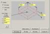
Hey guys, this is something minor, or more of just a pain in the xxxx but it seems to be doing it everytime I draw surfaces. I'll use my latest part as an example. I need a 6x6x1/2 plate with a hole in the middle. Simple enough. I drew the part and when I go to stock set up, I select "all surfaces" but it always adds .0002 to the stock origin in all axis. Is there something up with my tolerances in cad or something? See screenshot. By the way this happens on every file I draw with surfaces. X7 SP2
-
Ahhh. Nicely done. Thank you much.
-
Ya I am not using the same geometry. Its in the same place but translated 1/2" above. Is that still considered the same geometry? I attached the file for easier diagnostics. Paris I looked at your sample. I understand what you did. However is there a way to have it pocket from inside the 2.5" area and machine out in a circle to the 4.5"? Basically that is what I'm trying to do. Perhaps the dynamic toolpaths are not what I should be looking at?
-
Ok for some reason i can't get a simple toolpath to work properly. Not sure what I am doing wrong. All I have is a 4.5" hole that needs to be machined out. i start with a 2.5" drill so basically there is a pilot hole of that size. I drew some geometry for the 2.5" hole and I can do area no problem by chaining the outside (4.5") however it cuts air (thinks the middle is still there). So I'm trying to get it to start at the 2.5" diameter(pilot hole). I tried different chaining methods and both core and area to see if I can get it to go but clearly I'm not chaining right. What I'm doing is chaining the 2.5" arc and the 4.5" arc as my machining region, then I have the 4.5" as my avoidance region. I try to generate a toolpath but it fails. I then tried adding the 2.5" arc as another avoidance region, still nothing. Help please, lol. I suspect the path would have to be Core seeing as I need to start outside of the machined parameters but if I add an avoidance region, it fails. If I don't ad the avoidance region, it cuts outside the 4.5" diameter. CIRCLE.MCX-7
-
Awesome. Appreciate the responses fellas. Good to know.
-
Great. thanks a lot.
-
Ok thanks. But when you actually do draw one, how do you do it?
-
Is there something in X7 that can draw a threaded hole? Or do you guys just draw the tap drill size and specify it needs to be threaded? I'd like to be able to draw the thread in the model except I don't know how to draw solids. Only surfaces.
-
You can use CamStudio recorder. Its free and works well. Just select a window where you want it to record. http://camstudio.org/
-
It was made in Mastercam but not as a solid, but rather surfaces. I click it and it highlights however it does not show up through the outside of the shaft so even though its highlighted, its still not visible. I tried the translucent as well but it didn't look right, lol. I will try the free tool from Verisurf. Thanks.
-
Hi guys, this may be a simple question but I am not sure how to do it if possible. I have multiple colors on a part right now and was wondering if I can get the colors to be somewhat transparent so that you can see the actual part from one view. Basically I have a shaft drawn and it is in an isometric view. I want to print it out except from that view you can't see the hole that is drilled from the end. I'd like to somehow highlight that hole so that from the isometric view, you know it is there. That make sense?
-
Up North in Sudbury. Been here since 2002.
-
Ahh. I took a CNC course back then at that college. I believe my teacher's name was Chris. (About 15 years ago or so) Forget the last name but he worked at Babcock and Wilcox.
-
lol, ya I like to use levels as well but those are not from me. I imported the dxf originally and was trying to show the guy from that file. I ended up using that file as my start. Never ended up deleting the levels from the whole assembly. I agree with you though about different colors. I typically change the colors around in a lot of my files for different reasons and of course different levels as well. Just a quick question, I notice you are in Kitchener. I used to live and work in Waterloo 11 years ago. May I ask where you work out of curiosity?
-
Yes. It was for 3D demonstration for someone who couldn't understand the 2D drawing. I was trying to explain to him but he couldn't see it. So I said, I'll just draw it for you.
-
Worked good. Thank you. I guess to trim surfaces I should always make sure they are extended past each other?
-
Hi guys, see attached part. I am trying to trim 2 surfaces to close the top of the part. I have trouble with this type of cad. Am I using the right trim? Can't seem to get it. I thought at first I might have to extend them and then trim them but I still can't get it right. Any help would be appreciated. ROUND BAR.MCX-7
-
Dynamic Milling with open pocket
Hertz replied to Justin Beebe at Folsom Tool's topic in Industrial Forum
I like it. I noticed on the first part it was attacking the part in sections. Is that just programmed different areas to avoid air cutting? I typically would chain the whole part and I notice I get lots of air cutting if I'm on climb only. Your video gave me some ideas. Appreciate it. Thanks -
That was it. Posted properly. Funny sometimes how we overlook the simple stuff.. Thanks again Maclaw.
-
Thanks, I will look at it at work tomorrow. Never even thought to look at the stock. I appreciate it.
-
This is the output its posting. Note all the way around the part, the speed exceeds my maximum feedrate of 250 while its in cut. Sorry for the long quote. I do not know how to make it small.
-
Hi Colin. I am using the High feed option to slow down corners. 1180 is too sudden on the machine. If I don't use it, the machine takes the corners too fast and hard. Instead of using the option on the machine for corner smoothing(long story it doesn't work good on our machine) I use the High Feed option in Mastercam. Is this not what its for? Maybe I misunderstand the whole idea behind it? I always thought that's what it was there for. I do have the back feedrate to 1180 but it is posting to those speeds while in cut, not on the back feedrate. Again this is the first time I see this. I agree with you and usually only gets to those high speeds on the back feedrate. But for some reason the settings I have is different. Maybe I should post the code so you can see what I mean?
