Tinyfxds
-
Posts
332 -
Joined
-
Last visited
Content Type
Profiles
Forums
Downloads
Store
eMastercam Wiki
Blogs
Gallery
Events
Everything posted by Tinyfxds
-
I have a bunch a holes in my part that need to be drilled and tapped for their respective Helicoils. 6-32, 8-32, 10-32 and 1/4-20. If I'm correct the Helicoil taps have the same pitch as the threads you are trying to helicoil right? So when I enter my pitch of .03125 (6-32, 8-32, 10-32) into Mastercam everything should be fine using a helicoil tap correct?
-
We are using backer plate clamped to the table.
-
We are drilling some small holes in plexiglass sheets that are stacked together. We are having a problem with the middle 2-3 sheets melting around the holes. We are using coolant and a full retract peck drill. Here are the parameters for the drills. No. 35 drill 1136 rpm @2.72 ipm No, 29 drill 1102 rpm @2.2 ipm No. 26 drill 1020 rpm @2.04 ipm Ltr. B drill 840 rpm @1.68 ipm Ltr. X drill 508 rpm @ 1.02 ipm
-
Ok. That makes sense. I think I only get that when programming for our OKK with Fanuc 30i control on it. I don't believe I've ever gotten the option on the Hurcos
-
We had a very old Hurco post that did the same thing. It would start drilling at your retract height which is fine until you want to move over clamps; setting the retract height to 1 inch meant that it would start drilling 1 inch above the part. If we used the Clearance plane, it would add the clearance plane to the drill depth. So if I put in a clearance plane of 3 inches it would want to drill 3 inches deeper. I would contact your reseller and have them look at it or have them send you a new post.
-
When selecting a drilling cycle I've noticed that sometimes the "subsequent peck" field is selectable and sometimes it is not. What determines whether this field is selectable or grayed out? Is there something in the tool parameters that allows this?
-
Thanks! Yet another reason I like Mastercam. Always multiple ways to do something.
-
I've never saved a stock model as an stl before. How would I go about doing that? If I just do a file save as, it doesn't work. Am I suppose to save it thru verify as an stl?
-
Thanks guys.
-
I will need to split up my file into 2 seperate files. I have a stock model of all the operations from setup 1 and 2. My second file will start with setup 3. I would like to save my stock model from the first file and import it into my second file. How do I do this. I'd like to create another stock model off of this for the setup 3 tool paths. Is this possible?
-
Thanks. I found that as well but I just don't get why it would be throwing a code like that. The program is the same as a thousand others I posted out.
-
We have an Okk VB35 with a Fanuc 31i controller on it. We keep getting an "abnormal end" alarm when loading the program. It will load the program but not run it. Any one have any experience with this error / alarm? I've got a call in to our machine vendor but while waiting I'm looking on the interwebs and can't find squat.
-
I believe you are on to something. I remember at my old job that we had a print come in with "J" and "n's" all over it and the font was the problem in that instance. Thanks for jogging my memory. It makes sense because even the true position datum call out's were J's and K's.
-
What does a lower case "n" mean when you see it next to a dimension on a print? I don't think I've ever seen that before.
-
I figured it out. For some reason when I moved my boundary out by .125" everything worked fine even though the boundary was on the outside of the block and I was cutting on the inside of the block
-
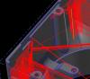
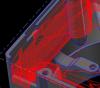
I'm roughing out a pocket with a 3' fly cutter and then want to rest mill with a 1.0" fly. The rest mill is not cutting a big area of the block and I can not get it to cut over that area no matter what I do. Now, here's the kicker, If I change the 3" to a 2" then the rest mill will work just fine. The first picture you see is the 3" and the second is the 2".
-
It works just fine. I printed out the list of tools I had and our tool vending machine took right where I needed to be.
-
It works! I forgot to read steps 6 and 7 after downloading the font.
-
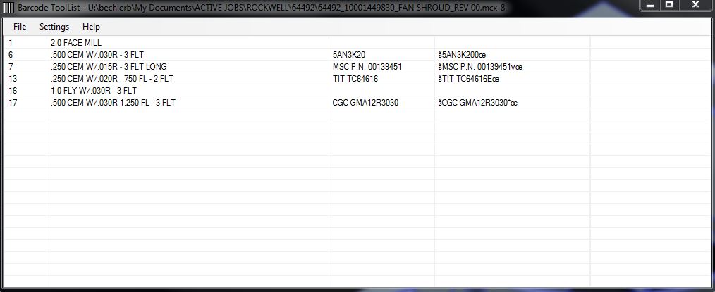
I downloaded a barcode font and copied it into where all the other fonts are. I'll have to try one more time.
-
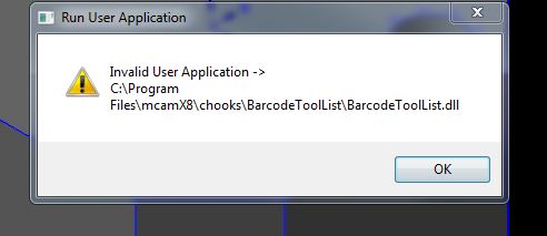
Ok I unblocked the file and it worked. This is what I got. I'm wondering if my barcode font is not correct?
-
I did have a go at it but keep getting an error that pops up. Not sure if I'm doing something wrong or not. I was going to read the instructions again and give it anther try.

-
I tried checking "disable hardware deceleration" didn't notice a difference in anything so I unchecked it and restarted Mastercam. This morning it seems fine so far.
-
So I shut down Mastercam and rebooted it. Now when ever I create or regenerate a tool path I have a read trace line that runs showing my tool path. It's a quick animated sequence but I don't like it and I can't seem to find where to turn it off. Anyone have and suggestions?
-
Thank you Derek. I will give it a try tomorrow.
-
The STL file I've saved from my verify is always in the wrong position when I select it to be my stock for the next setup verify. What am I missing here? It always brings the STL in orientated in the Setup One view which is 180 degrees off from my setup two view. I know I'm missing something easy here.