Spotterhphc
-
Posts
82 -
Joined
-
Last visited
Content Type
Profiles
Forums
Downloads
Store
eMastercam Wiki
Blogs
Gallery
Events
Everything posted by Spotterhphc
-
Hey I've seen this for years and and until now have just managed . If I am interpolating some holes whose geometry is identical to one another, mastercam/post outputs the I/J code .0001 different usually when the holes are in different quadrants. Making it a pain to dial in a tight bore. If I change the tool diameter by .00005 then they all post the same. Where is this tolerance rounding happening and how do I make a perm fix? See the sample code below. It's easy enough to just add .00005 to the tool diameter but if I forget then..... Thanks! X5.8987 Z-.3825 I.0237 J0. X5.8513 Z-.395 I-.0237 J0. X5.8987 Z-.4075 I.0237 J0. X5.8513 Z-.42 I-.0237 J0. X5.8987 Z-.4325 I.0237 J0. X5.8513 Z-.445 I-.0237 J0. X5.8987 Z-.4575 I.0237 J0. X5.8513 Z-.47 I-.0237 J0. X5.8987 Z-.4825 I.0237 J0. X5.8513 Z-.495 I-.0237 J0. X5.8987 Z-.5075 I.0237 J0. X5.8513 Z-.52 I-.0237 J0. X5.8987 Z-.5325 I.0237 J0. X5.8513 Z-.545 I-.0237 J0. X5.8987 Z-.5575 I.0237 J0. X5.8513 Z-.57 I-.0237 J0. X5.8987 I.0237 J0. X5.8513 I-.0237 J0. X5.8533 Y-.2717 I.0237 J0. X5.8665 Y-.2767 I.0091 J.0041 G01 G40 X5.8757 Y-.2727 Z-.55 F50. G00 Z.25 X6.2712 Y-.222 Z.025 G01 Z.005 F25. G41 D3 X6.2612 F20. G03 X6.2512 Y-.232 I0. J-.01 X6.2988 Z-.0075 I.0238 J0. X6.2512 Z-.02 I-.0238 J0. X6.2988 Z-.0325 I.0238 J0. X6.2512 Z-.045 I-.0238 J0. X6.2988 Z-.0575 I.0238 J0. X6.2512 Z-.07 I-.0238 J0. X6.2988 Z-.0825 I.0238 J0. X6.2512 Z-.095 I-.0238 J0. X6.2988 Z-.1075 I.0238 J0. X6.2512 Z-.12 I-.0238 J0. X6.2988 Z-.1325 I.0238 J0.
-
indeed it is. This was just a test cut so I "knew" it would clear. There was a bit of pucker factor going for a min I wont lie.
-
Well I tinkered with it for a little bit and was able to hand program it. Pretty Simple when it cam down to it. Just make sure you don't have any spindle and feed overrides active and don't feed hold. Not sure if .MOV attachments work but here is a quick clip. N3401 T34 T0 M6 (0.236 FLAT ENDMILL) (F71.484) (OPERATION NO - 1) G10.9 X0 M901 M200 G91 G00 G28 X0. G17 G90 G54 M108 M212 B90. C90. M107 M19S180. G68.2 P1 X0. Y1.9827 Z0. I0. J90. K90. G53.1 G97 G43 H#3020 X.5689 Y0. Z.25 G17 Z.2 G94 G01 Z0. F25. M51 G02 X.5689 Y0. Z-.005 I-.5689 J0. F71.484 S20 M3 X.5689 Y0. Z-.01 I-.5689 J0. X.5689 Y0. Z-.015 I-.5689 J0. X.5689 Y0. Z-.02 I-.5689 J0. X.5689 Y0. Z-.025 I-.5689 J0. X.5689 Y0. Z-.03 I-.5689 J0. X.5689 Y0. I-.5689 J0. X.5689 Y0. Z.005 I-.5689 J0. G1 Z.17 F50. G00 Z.25 M9 M5G69 G91 G28 X0. Y0. G28 Z0. IMG_2772.MOV
-
better yet at 4min 5sec is exactly what I need
-
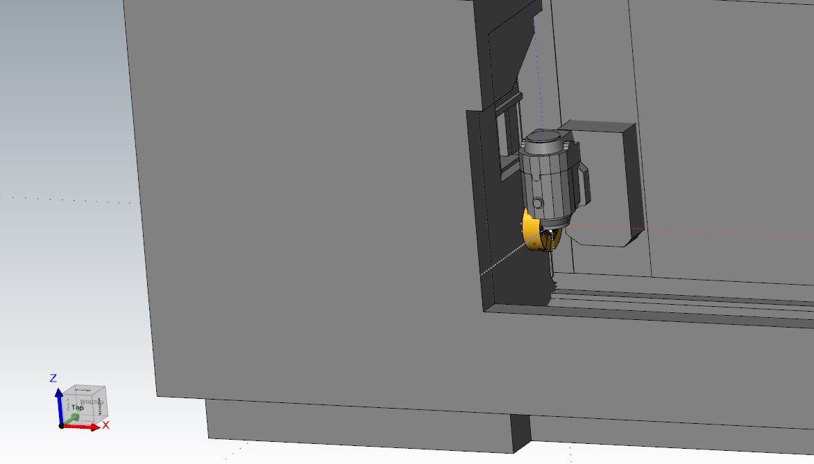
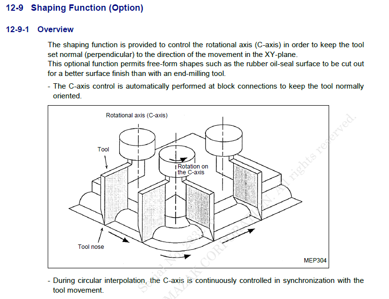
So my plan is to use a Face Groove Tool, Sandvik# CXS-06F150-6215AR. I can't use this tool without Syncing the Mill spindle Speed with what would be my YZ at B90. Currently I am using an Endmill to generate this feature but I have to go back through and sand the O-ring to give it a circular finish per print. So a face groover would give me this finish. My reason for thinking shaping is because the actual Spindle speed would be like 10rpm or something all the while keeping the tool outer tip at the correct diameter. Thanks for the timely responses! This is essentially what it's needs to do. This is the Orbit option but its similar. Or are you saying just figure out my SFM that I want and my center point of arc and then find my Feed based on that? If that makes sense.
-
Looking at the manual it seems like it's saying it wants to use the C-Axis. I'm probably reading this wrong.
-
Hey, I did a search and couldn't find anything on this topic. I am looking to use the shaping option Mazak offers on my Integrex i300. The feature on the part is just a simple o-ring groove that is 1.37" major diameter ( correct terminology for grooves? ). Not very big at all. My question is, has anyone ever written a program for Shaping before and willing to share some sample code? I've been studying the manual trying to make sense of it buuuuttt...... The groove will be machined at B90.° so the C axis will not be used except to position the groove top surface. It's just a flat O-Ring Groove. I'm working on getting the Shaping Option as we speak. The Orbiturn option I do not believe is necessary. Thoughts/concerns? Thanks for the help!
-
Wow look at the all these suggestions. Thanks everyone. I'll give these a try and see what works best for my flow. The post automatically determines the G10.9 values depending on the operation type. The reason i was thinking of using the same machine Def and post was to utilize the B90° rotation that is necessary after every tool change. Ill look over these comments closer see I can make sense of all this. This is great reading material for at night.
-
Hello, Recently I made a table that goes on my Integrex i300, so now I am able to mount two 6" vises in the machine to allow for easy 3X mill work ( it's the bees knees ). I am wondering if there is a way to set some custom planes so when I select my machine definition it defaults to these planes. I want to copy my machine def and make it specific to 3X milling using the lathe machine def. Currently I am aligning the parts to Mastercam World XYZ (d+z+). I don't want my post to post out G68.2. I turn it off in the post only the post doesn't post out xyz correctly per the machines layout. Is there a way to be able to have the post manipulate the XYZ to match the machine def layout? i.e. x+=mcam z+ and z+= mcam x+ What I want to be able to ultimately do is program as if i were programming a 3 axis vertical mill where I can set my part to World XYZ (TOP) and take off. I don't want to have to set WCS to D+Z+ (TOP) and a Tplane that is 90° to that. It just makes for one more thing to miss before posting. If by default everything was top/top and the post figured it all out then I'd be a happy camper. Wow, rereading that just sounds confusing. Thanks for any input
-
Forcing arcs into line segments for better accuracy?
Spotterhphc replied to machineimpossible's topic in Industrial Forum
In those cases i have had really great luck kicking the part at an angle and using a ball em to surface the corner. Yes it does take longer but given you have a machine that has 5x capabilities and it is really tight (center of rotation is dialed in ) then it works great. Blending two tools isn't ideal but again, if the machine is tight then it's no issue. Also have used a ball em of equal radius as the part fillet and used multiaxis morph to drive the tool using 1 pass (determined by number of cuts, area type) That is my preferred method because the surface finish is beautiful especially in aluminum. Only using 3 axis is preferred but if the machine is tight then use the features you paid for. -
Machine Simulation - MASTERCAM 2019-2020
Spotterhphc replied to Ucuellar2011's topic in Machining, Tools, Cutting & Probing
For anyone who may want it I drew up a detailed model of an Integrex MIll head. The casting sections of the head are probably within .02" but everything else, for my machine anyway, is within .005. Way more detail than we need so i saved it as a .stp so you can modify to suite your needs. Mazak wanted $2000 for this model so I took an hour or so and drew it myself. Enjoy INTEGREX-MILL-HEAD.stp -
Machine Simulation - MASTERCAM 2019-2020
Spotterhphc replied to Ucuellar2011's topic in Machining, Tools, Cutting & Probing
Wow, ok sorry I just saw that you replied. Thanks for files and all the help. I dont have a post linked to it yet. Is that something you recommend? -
Machine Simulation - MASTERCAM 2019-2020
Spotterhphc replied to Ucuellar2011's topic in Machining, Tools, Cutting & Probing
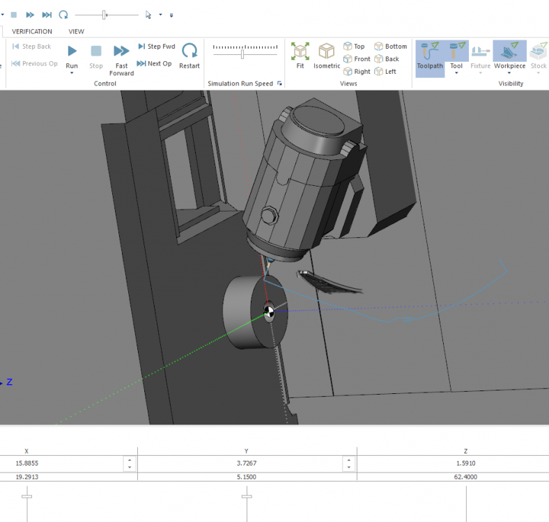
Sorry, I thought i put the gnomon in the screen shot. Here it is now. Right after I sent that last response I looked at Ucuellar2011 images again and noticed that the B-axis slider had +120° and -120° for values instead of the -30° and +210°. So that gave me the thought that maybe the B-axis needs to be perpendicular to C. I tried saving the B-axis STL in that 90° position and it worked ( for milling ). The image shows the new orientation when all axis are at zero position. The only issue is that the turning tools won't rotate the B. They only display at the 90° position. The B-axis stays fixed. Can I just say that forums are great and I can't imagine life without em now. This is an extremely valuable tool emastercam. Just wish I had something to contribute. Maybe an edible arrangement will suffice. Thanks for all the help again.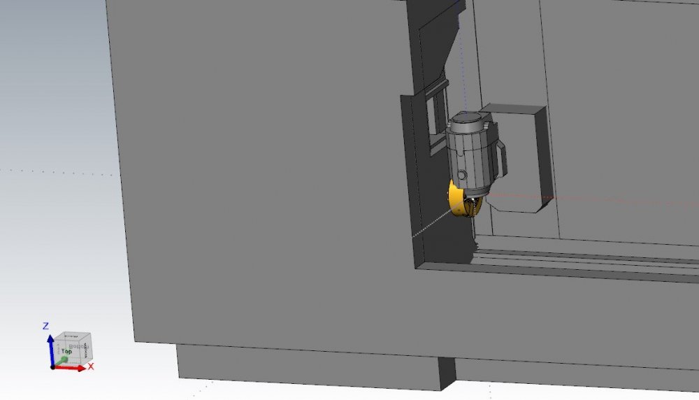
-
Machine Simulation - MASTERCAM 2019-2020
Spotterhphc replied to Ucuellar2011's topic in Machining, Tools, Cutting & Probing
Yes. I made it so Mastercam World Z is is the machines X. Should I move the stl 90° so it is perpendicular to the lathe chuck? When all axis are set to zero this is how it sits.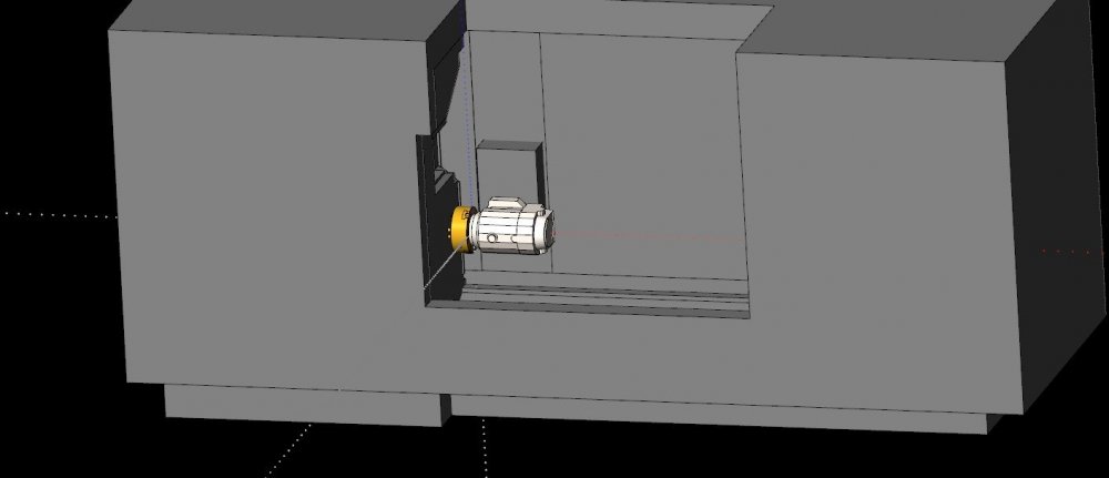
-
Machine Simulation - MASTERCAM 2019-2020
Spotterhphc replied to Ucuellar2011's topic in Machining, Tools, Cutting & Probing
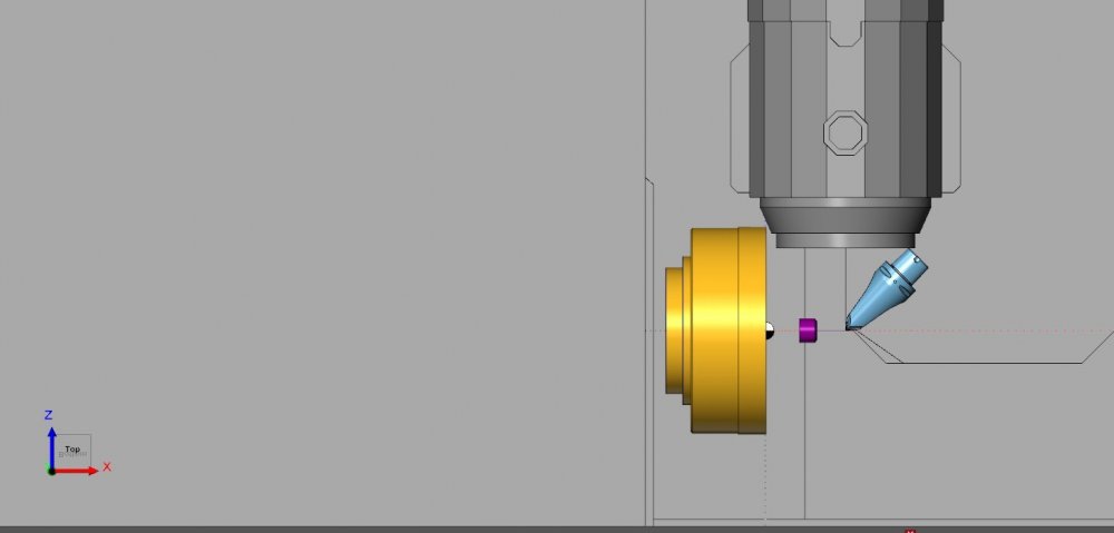
I am looking for a similar set up only for an i300w. I am really close to getting it ( i think I am) but am hung up on the holder coming in 90° off. Does anyone have an idea on how to fix that? I was trying to follow Ucuellar2011 build since it's a similar machine but now I'm stuck. I tried the " holder_transform" but i keep getting this gimbal lock. I wish I new more. I can run the sim with the holder 90° off and it looks like it's moving all axis the way it's supposed to so it's close. Thanks for any help.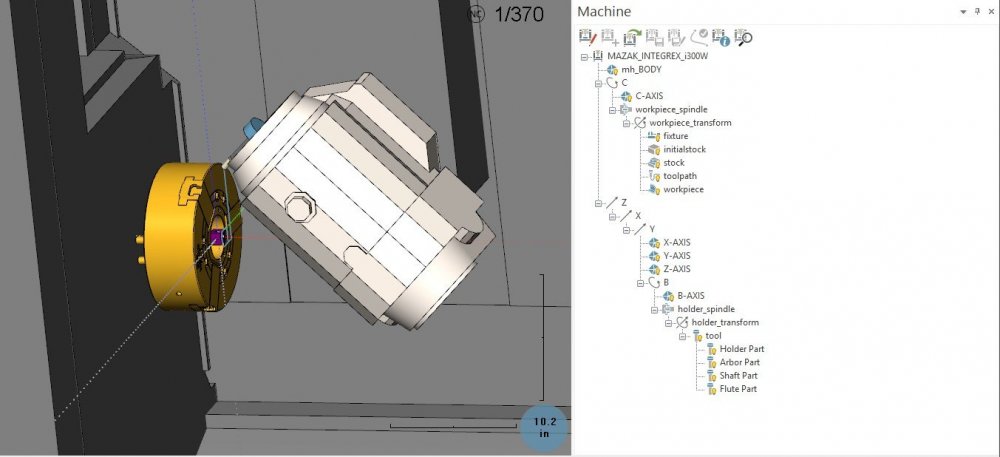
-
Verisurf CMM Reviews Needed ( unbiased preferred )
Spotterhphc replied to Spotterhphc's topic in Industrial Forum
This is great info thanks! It's great to hear from real world people. We only have fixed cmm's at this shop but would like to implement new technology when the time is right. Our sister shop has fixed machines and a smart scope for optical measurements. I don't know much about the CMM world but i know enough to see the advantages of great software. We are currently doing D6-51991 work but use other validation software. Thanks for the help! -
Hi there, We are an aerospace shop and we are considering Verisurf for our inspection department metrology equipment. Curious if anyone on here has used it in the past or is currently using it and what do you think of it. Did it truly help the way you were hoping? We currently have one lead inspector who uses PC-Dmis and if he ever leaves we are screwed. From what I have seen in videos and what i have played with in the free version it is super super intuitive. Plus, it sits in the Mastercam Platform making transitions easier. It is a little spendy but if a machine sits for an hour or more at a time waiting on a first article then it won't take long to see returns. Thanks for the info!
-
Using 2019 mcx and 2019 library. the specific tool is manufacture# 3540L.12200A. 42.5° taper form. Tool Holder is Sandvik 12mm Hydraulic pencil Capto C6 Step over has been .04-.05. material to remove is .01 i do have 2020 installed i just haven't moved over yet with this part file. Thanks
-
Hello, I am currently toying with Taper Form tools, as many people are these days, but am having a hard time getting the surface finish I desire. I contacted Emuge and spoke with an engineer and was given parameters to start with. They were pretty dang close. I have narrowed down the possible reasons for poor finish and landed on tolerance within the toolpath. I am using multiaxis parallel and have tried a number of things to remedy this. Does anyone have any experience with these tools and this toolpath and know a good "cut tolerance, max distance" that will make great surface finishes? Or anything at all. I have tried anywhere from .00005 cut tolerance and .002 max distance, up to .0002 cut tolerance and .02 max distance and a few in between. The surface is ever changing in all directions. Very gradual, but changing. For scale, the surface is 37" from tip to tip. A Pringle potato chip is the best explanation as to how the surface changes in all directions. XYZ Thanks for any input

-
No it's not currently attached. I was just looking into that this morning but can't find much on what steps to take to do that. Is this a reseller question? Thanks!
-
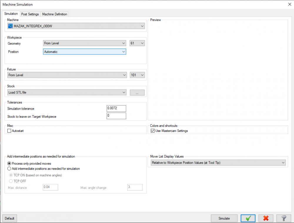
Hello All I am seeking help on Mastercam Simulator with regards to part position. As you can see in the picture attached, the part is positioned through my Z axis cover. My XYZ+ directions are all in the proper direction per the machine. I played with "workpiece_transform rotaion about Y " to get the part to visually look correct but i can't get it to stay that way and simulate correctly. I know this isn't much info, so ask me what you need and ill try to answer. Thanks in advance!
-
No I am not. Just simple contours, drilling, dynamic mill.
-
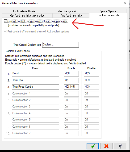
Hello helpful people, Has anyone ever ran into the post not posting coolant on every tool change? I've double checked that coolant is turned on in all ops but for some reason it only posts M08 on the very first tool. Have any clue as to where i n the post this is located? Thanks for any help, MAZAK-4X.mcpost MAZAK-4X.mcam-mmd MAZAK-4X.mcam-control
-
Thanks for all the responses. So what worked for me was to update the coolant codes in the post and use this button It all works fine now because the post forces it to go to a said location. I was un checking that check box.
-
Hello I searched but didn't find anything to help with this simple problem. I need my operation default for coolant to be set to "after" for all operations. It currently sets itself to "before" and when I go into the control def and edit all selected ops to change the default, the "before/with/after" tab is grayed out so i can't change it. What am i doing wrong here? I currently have to manually change it to "after" on every operation. Thanks for any advise and if there is a thread currently out there just send it my way.