Search the Community
Showing results for tags 'Rotary Axis'.
Found 5 results
-
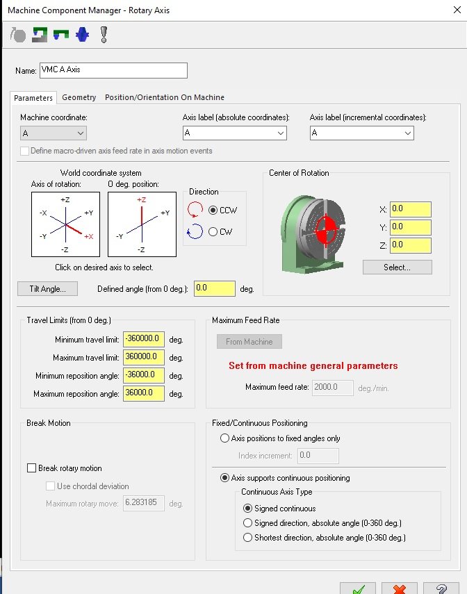
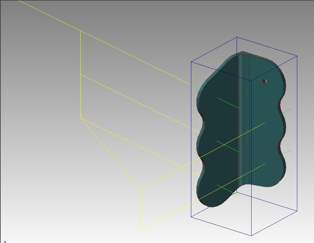
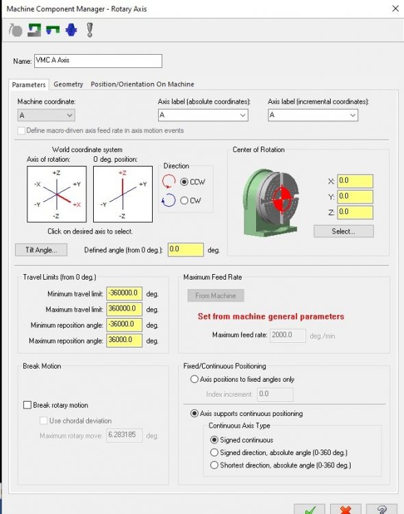
Hi Everybody, I have a round part with some internal features that were milled on a VMC and now I have to add a port hole to match up with the inside. There are also many other holes on the OD of the part so I am using the 4th axis. So when I made my Setup Sheet I said to indicate a given surface flat and set that to A0. Which makes the first hole directly on top of the part (from Top View). Problem is when I post that first whole that is directly on top posts as A-180. I hadn't noticed this with my 4th axis post here before because I wasn't matching up previous ops. Correct me if I am wrong but shouldn't A0. be the "top" and not require rotation. Please help me fix this I'm guessing the Machine Component Manager-Rotary Axis page is where to fix it but I am not sure as what to do?
-
Another GoPro Video. This time rotary peel milling on our VM3 with HRT210 4 axis. Using axis substitution. Material: A2: Tool: 3/8 IMCO power feed .02CR 600 SFM (6112 RPM) .004 FPT (146.69 IPM) 7% Step over (.027) .570 DOC
-
Ok, I have the rotary active in MC. I'm doing a full rotary groove that's about 7000 deg of turning. The max federate on this rotary is 60 deg/sec. I want a F50.0 to post out. what is the correct way of calculating this? MC is giving me a strange federate. If I put 8.37 in the federate box I get 50.0 posted out. What is MC using to calculate The rotary is 8.0 inches dia. The part is 10.0 dia. Any one?
-
 I'm having trouble editing my post to give me a work offset call with a G90 A0. at the end of my program. This is where I am trying to put it in my post: peof$ #End of file for non-zero tool pretract comment$ if stagetool = 1 & stagetltype = 2, pbld, n$, *first_tool$, e$ n$, *sgcode, *sgabsinc, pwcs, "A0.", e$ <------- the line I have added. n$, "M30", e$ Not sure what I'm doing wrong to get a output of G54, G55, etc. This is what it is posting: G0 Z1.1 M9 G91 G28 Z0. M5 G28 Y0. G0 G90 A0. M30 % And this is what I want: G0 Z1.1 M9 G91 G28 Z0. M5 G28 Y0. G0 G90 G54(or whatever work offset program is using) A0. M30 % Thank you
 -
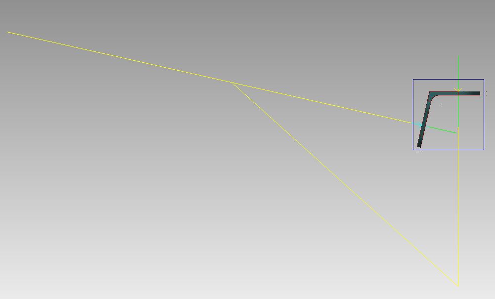
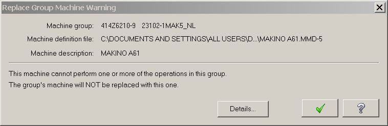
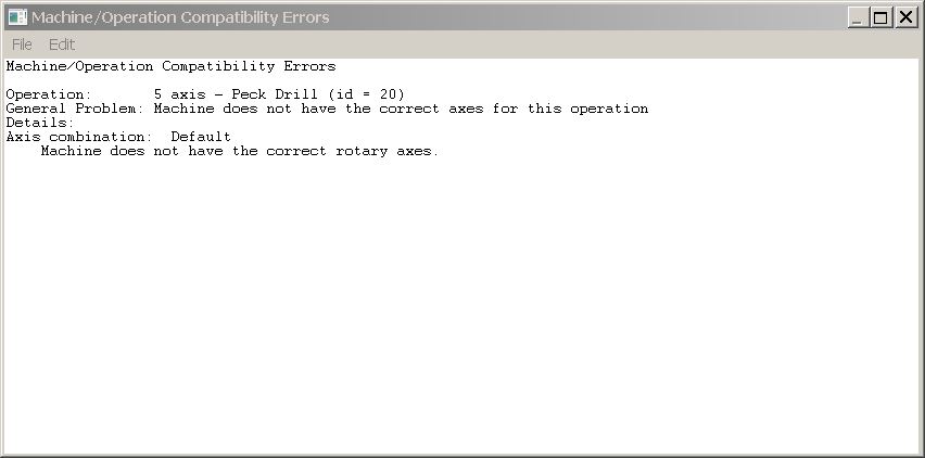
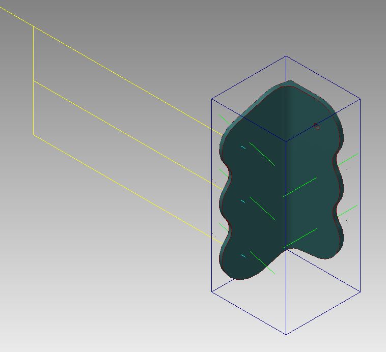
Has anyone else seen this? It appears to be a bug going back to at least X5 and still present in X7. We are running 4-axis horizontal Makino A61's. All paths are set with WCS to TOP and any Tool/Const Planes set as needed. i.e. Front, Left Side, Custom, etc. In the 5-Axis Drill operation parameters under the Tool Axis Control there is a Rotary Axis setting for X, Y, or Z. Mastercam Help says this setting is based on WCS so since our B-axis (rotary) is about the Z-axis that is what is selected and Mastercam says it's valid. However, the code is wrong and back plot reflects it. In order to get the correct code this must be set to Y-axis. However, when you reopen the file it goes dirty because Mastercam says the path is not valid with the Machine Definition. Is no one using 5-Axis Drill? Or are we doing something wrong? I have tested this on the supplied Mastercam MD/CD's as well as the custom ones we use. No change. We have tried all logical WCS, TP, CP combinations with incorrect code results. Thanks, -Pat