Matt Berube at Ferron Mold
-
Posts
1,467 -
Joined
-
Last visited
Content Type
Profiles
Forums
Downloads
Store
eMastercam Wiki
Blogs
Gallery
Events
Everything posted by Matt Berube at Ferron Mold
-
 Thanks guys, I am now calling Makino to figure out whether something needs to be unlocked in the control.
 -
Still experimenting... Changed the "minimum inverse feed rate" to 20,000 minutes... Now the post is no longer hitting the minimum feed rate limit but why are the feedrate numbers so large? % O0010 (KK2626 SLEEVE MILLING) (MAKINO A-61) (MACHINE GROUP-1) (MCX FILE - S:\MCX\KK2626\KK2626 SLEEVE MILLING.MCAM) (PROGRAM - KK2626 SLEEVE MILLING.NC) (DATE - AUG-20-2018) (TIME - 9:15 AM) (T41 - .0625 CARB MILL - H41 - D41 - D0.0625") N100 G00 G17 G20 G40 G80 G90 N110 G91 G28 Z0. N120 (COMPENSATION TYPE - COMPUTER) N130 T41 M06 ( .0625 CARB MILL) N140 M11 (UNLOCK) N150 G00 G17 G90 G54 B30. X0. Y-3.2337 S10000 M03 N160 G43 H1 Z1.2188 N170 M08 N180 Z.6188 N190 G94 G01 Z.2188 F3. N200 G93 X-.0039 Z.2187 B31.555 F9850.9 N210 X-.008 B33.182 F9374.62 N220 X-.0123 B34.884 F8886.34 N230 X-.0167 B36.664 F8386.92 N240 X-.0214 B38.524 F7874.14 N250 X-.0262 B40.466 F7409.03 N260 X-.0312 B42.497 F6810.91 N270 X-.0313 Y-3.231 B42.5 F7344.41 N280 G94 Y-3.228 F20. N290 Y-3.2248 N300 Y-3.2212 N310 Y-3.2172
-
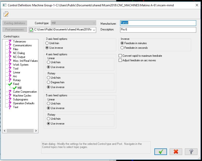
Greetings fellow Mastercammers, I have an MP Master post which I muddled my way through setting up myself for our Makino A-61 with Pro6 control. It works great for everything we've done so far but now that I'm needing to mill with the B axis, I'm forced to learn about inverse time feedrates... I have a couple concerns at the moment: 1. The G93 feedrates post out at the minimum. Mastercam posts whatever I set the "inverse time feed rate limits" (minimum) to. In the snippet below, my inch Inverse Time Feedrate Limit was set at 333 minutes. % O0010 (KK2626 SLEEVE MILLING) (MAKINO A-61) (MACHINE GROUP-1) (MCX FILE - S:\MCX\KK2626\KK2626 SLEEVE MILLING-TEST.MCAM) (PROGRAM - KK2626 SLEEVE MILLING.NC) (DATE - AUG-20-2018) (TIME - 8:39 AM) (T41 - .0625 CARB MILL - H41 - D41 - D0.0625") N100 G00 G17 G20 G40 G80 G90 N110 G91 G28 Z0. N120 (COMPENSATION TYPE - COMPUTER) N130 T41 M06 ( .0625 CARB MILL) N140 M11 (UNLOCK) N150 G00 G17 G90 G54 B30. X0. Y-3.2337 S10000 M03 N160 G43 H1 Z1.2188 N170 M08 N180 Z.6188 N190 G94 G01 Z.2188 F3. N200 G93 X-.0039 Z.2187 B31.555 F333. N210 X-.008 B33.182 F333. N220 X-.0123 B34.884 F333. N230 X-.0167 B36.664 F333. N240 X-.0214 B38.524 F333. N250 X-.0262 B40.466 F333. N260 X-.0312 B42.497 F333. N270 X-.0313 Y-3.231 B42.5 F333. N280 G94 Y-3.228 F20. N290 Y-3.2248 N300 Y-3.2212 N310 Y-3.2172 N320 Y-3.2129 N330 Y-3.2082 N340 Y-3.203 N350 Y-3.1973 N360 Y-3.1911 N370 Y-3.1842 N380 Y-3.1767 N390 Y-3.1685 N400 Y-3.1595 N410 Y-3.1496 N420 Y-3.1388 2. See in pic below where "use inverse" is specified in every place possible. I can't understand why with the selections made below, the NC file still switches back and forth between G93 and G94. In my "Swarf Milling" operation, the feedrates for the tool are set to "Plunge = 3.0, Feed 20.0, Retract 20.0" If somebody could point me in the correct direction I'd appreciate it
-
I was close to asking that too but after testing myself, I think I figured out why. My example file had just 1 pocket. It seems that Mastercam's specification is that within a single contour, the RETRACT value is used. If you were to take my example file and delete the chain I have in the operation and then draw 2 rectangles and chain both of them, you will see the different output depending upon whether the box is checked or not. Basically, within a single contour, you will get the retract. With more than 1 contour, you'll get the retract within each contour but then the clearance will be used when traveling between contour #1 and contour #2.
-
As designed, apparently. Here's the official (very speedy too!) response from QC. "I tested in X9 and 2017 and 2018 is working the same way X9 and 2017 worked. If you want the tool to go to the 2” clearance plane, uncheck Retract."
-
I sent it up to QC. I'll update here when they respond.
-
Sorry I wasn't clear enough CM Check out this file if you have a minute. I expect 2.0 CLEARANCE moves throughout this operation but they are only happening at the beginning and end. clearance problem.mcam
-
I am using 2-D toolpaths (face, contour) and I have "clearance" checked in Linking Parameters with an Absolute value of 2.0 "Use only at the start and end of the operation" is not checked. Ignoring the settings above, Mastercam is only using the clearance value at the beginning and end of the operation. All other moves are only retracting to the "Retract" plane. Is this broken in 2018? Anybody else having this difficulty?
-
Windows 10 1709 update issues update
Matt Berube at Ferron Mold replied to Jayson Kramer's topic in Industrial Forum
EXTREMELY HAPPY THIS IS FIXED!!! Sorry about the shouting. I am pretty excited. That lag was brutal. Mastercam 2017 and 2018 running fast and smooth with fully patched Windows 10. -
Manager Icons are tiny!
Matt Berube at Ferron Mold replied to morrissouth's topic in Industrial Forum
Not sure what the problem is... Did you re-start the computer? Here's my setup... The large icons are working great for me.
-
I had the same gripe until I noticed there are 2 places to initiate a search...

-
Is M255 for GI/Super-GI Radical Mode on your machines? Is that what you use for everything or do you change it up depending upon the current job?
-
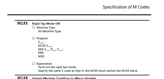
Since you recommended the Fadal post, I started trying to figure out how to apply it to the MPMaster. I don't know much of anything about posts but I'm trying. I acquired the full MP_documentation 4.04 PDF portfolio to begin making sense of it all. Ran the debugger on the Fadal and found out a bunch of stuff I don't really understand yet. One big difference I note between MP Master and the Fadal Generic is that MP Master has a rigid_tap variable built in and it seems that the Fadal post uses "opcode" statements. Am I correct to believe that MPMaster uses rigid_tap instead of opcode to make the post easier to follow and edit? I couldn't really figure how to apply anything from the Fadal post to MPMaster but I was able to modify MPMaster to give the output I desire. Here's what I did: ptap$ #Canned Tap Cycle pdrlcommonb #RH/LH based on spindle direction if rigid_tap, pbld, n$, *speed, *spindle, e$ #mab12-13-17 added this line if rigid_tap, pbld, n$, *sm29, *speed, e$ #Rigid Tapping if use_pitch = 0, [ pcan1, pbld, n$, *sgdrlref, *sgdrill, pdrlxy, pfzout, pcout, pindexdrl, prdrlout, [if peck1$, *peck1$], *feed, strcantext, e$ ] else, [ if metvals, pitch = n_tap_thds$ # Tap pitch (mm per thread) else, pitch = 1/n_tap_thds$ # Tap pitch (inches per thread) pcan1, pbld, n$, *sgdrlref, *sgdrill, pdrlxy, pfzout, pcout, pindexdrl, prdrlout, [if peck1$, *peck1$], *pitch, !feed, strcantext, e$ ] pcom_movea And here is the NC Output: N390 M01 N400 T50 M06 ( 10-32 TAP) N410 (MAX - Z2.) N420 (MIN - Z-.4) N430 G00 G17 G90 G54 B0. X-2. Y1.125 N440 G43 H1 Z2. N450 G94 N460 S300 M03 N470 M135 S300 N480 G98 G84 X-2. Y1.125 Z-.4 R.1 F9.38 N490 X2. Y1.125 N500 X2. Y-1.125 N510 X-2. Y-1.125 N520 G80 N530 M05 N540 G91 G28 Z0. N550 M01 N560 T37 M06 (LEFT HAND 10-32 TAP) N570 (MAX - Z2.) N580 (MIN - Z-.4) N590 G00 G17 G90 G54 B0. X-2. Y1.125 N600 G43 H1 Z2. N610 G94 N620 S300 M04 N630 M135 S300 N640 G98 G74 X-2. Y1.125 Z-.4 R.1 F9.38 N650 X2. Y1.125 N660 X2. Y-1.125 N670 X-2. Y-1.125 N680 G80 N690 M05 N700 G91 G28 Z0. N710 M01 The .NC code is exactly what I was aiming for and seems to handle LH/RH taps perfectly. My only question is whether I've gone about this in the proper way. Is there anything wrong with this method? Also, not sure what you were trying to show me in the Fadal post. That seems to be beyond my grasp without further explanation.
-
I do have that post but I dunno what to do with it... Generic Fadal Format_1 4X Mill Post: ptap$ #Canned Tap Cycle - G84/G74 pdrlcommonb if tap_format = 2, [ feed = (1 / n_tap_thds$) * speed pcan1, pbld, n$, *sgdrill, *sgdrlref, pfxout, pfyout, pfzout, pcout, prdrlout, *feed, dwell$, strcantext, e$ ] else, [ feed = speed thread_lead = 1 / n_tap_thds$ pcan1, pbld, n$, *sgdrill, *sgdrlref, pfxout, pfyout, pfzout, pcout, prdrlout, *feed, *thread_lead, dwell$, strcantext, e$ ] pcom_movea
-
This is the code I am currently getting: N590 T50 M06 ( 10-32 TAP) N600 (MAX - Z2.) N610 (MIN - Z-.4) N620 G00 G17 G90 G54 B0. X-2. Y1.125 N630 G43 H1 Z2. N640 G94 N650 M135 S300 N660 G98 G84 X-2. Y1.125 Z-.4 R.1 F9.38 N670 X2. Y1.125 N680 X2. Y-1.125 N690 X-2. Y-1.125 N700 G80 N710 M05 N720 G91 G28 Z0. N730 G28 Y0. B0. N740 G90 N750 M30 This is from the M Code Specifications: This is the code I desire: N590 T50 M06 ( 10-32 TAP) N600 (MAX - Z2.) N610 (MIN - Z-.4) N620 G00 G17 G90 G54 B0. X-2. Y1.125 N630 G43 H1 Z2. N640 G94 N645 S300 M3 <<<<<<<<<<<<<<<<<<<<<<<<<<<<<<<<<<<<<<<<< N650 M135 S300 N660 G98 G84 X-2. Y1.125 Z-.4 R.1 F9.38 N670 X2. Y1.125 N680 X2. Y-1.125 N690 X-2. Y-1.125 N700 G80 N710 M05 N720 G91 G28 Z0. N730 G28 Y0. B0. N740 G90 N750 M30 And here is a snip from the post: ptap$ #Canned Tap Cycle pdrlcommonb #RH/LH based on spindle direction if rigid_tap, pbld, n$, *sm29, *speed, e$ #Rigid Tapping if use_pitch = 0, [ pcan1, pbld, n$, *sgdrlref, *sgdrill, pdrlxy, pfzout, pcout, pindexdrl, prdrlout, [if peck1$, *peck1$], *feed, strcantext, e$ ] else, [ if metvals, pitch = n_tap_thds$ # Tap pitch (mm per thread) else, pitch = 1/n_tap_thds$ # Tap pitch (inches per thread) pcan1, pbld, n$, *sgdrlref, *sgdrill, pdrlxy, pfzout, pcout, pindexdrl, prdrlout, [if peck1$, *peck1$], *pitch, !feed, strcantext, e$ ] pcom_movea What do I need to add?
-
Thanks for the help, Zoober!
-
Your research was correct, Husker! I needed an M135 instead. That was almost too easy! N1230 M01 N1240 T50 M06 ( 10-32 TAP) N1250 (MAX - Z2.) N1260 (MIN - Z-.4) N1270 G00 G17 G90 G54 B0. X-2. Y1.125 N1280 G43 H1 Z2. N1290 G94 N1300 M135 S300 N1310 G98 G84 X-2. Y1.125 Z-.4 R.1 F9.38 N1320 X2. Y1.125 N1330 X2. Y-1.125 N1340 X-2. Y-1.125 N1350 G80 N1360 M05 N1370 G91 G28 Z0.
-
Thank you! I'll check it out.
-
Next issue is with rigid tapping. Here is the bad code: N1220 G91 G28 Z0. N1230 M01 N1240 T50 M06 ( 10-32 TAP) N1250 (MAX - Z2.) N1260 (MIN - Z-.4) N1270 G00 G17 G90 G54 B0. X-3. Y1.125 N1280 G43 H1 Z2. N1290 G94 N1300 M29 S300 N1310 G98 G84 X-3. Y1.125 Z-.4 R.1 F9.38 N1320 X1. Y1.125 N1330 X1. Y-1.125 N1340 X-3. Y-1.125 N1350 G80 N1360 M05 N1370 G91 G28 Z0. N1380 M01 What would be the best way to output S300 M3 before the M29? Should I put it on the G43 line? The problem we had with code posted above is that the spindle stays off until it reaches the bottom of hole #1 then reverses out and proceeds to tap the remaining holes properly... So the spindle must be started before the M29 - and I'm told the M29 should be on a line of it's own.
-
Success! % O0002 (Makino Post Test 2) (MAKINO A-61) (MACHINE GROUP-1) (MCX FILE - S:\MCX\MAKINO\MAKINO POST TEST 2.MCAM) (PROGRAM - Makino Post Test 2.NC) (DATE - DEC-07-2017) (TIME - 1:05 PM) (T54 - 2.00 ISCAR INS MILL - H54 - D54 - D2.0000" - R0.0300") (T15 - .500 CARB FIN. MILL - H15 - D15 - D0.5000") (T9 - 1.125 CHAMFER MILL *.625 SM.DIA.* - H9 - D9 - D1.0440" - R0.0200") (T2 - .250 CTR DRILL - H2 - D2 - D0.2500") (T4 - .159 DRILL NUM21 - H4 - D4 - D0.1590") (T50 - 10-32 TAP - H50 - D50 - D0.1900") (T36 - 1.00 B BAR - H36 - D36 - D1.0000") (OVERALL MAX - Z2.) (OVERALL MIN - Z-.5) N100 G00 G17 G20 G40 G80 G90 N110 G91 G28 Z0. N120 (COMPENSATION TYPE - COMPUTER) N130 T54 M06 ( 2.00 ISCAR INS MILL) N140 (MAX - Z2.) N150 (MIN - Z0.) N160 G00 G17 G90 G54 B0. X-5.5691 Y1.4999 S850 M03 N170 G43 H1 Z2. T15 N180 Z.1 N190 G94 G01 Z0. F20. N200 X2.5691 F11.5 N210 X2.575 Y.5 N220 X-4.575 N230 Y-.5 N240 X2.575 N250 X2.5691 Y-1.4999 N260 X-5.5691 N270 G00 Z2. N280 M05 N290 G91 G28 Z0. N300 M01 N310 (COMPENSATION TYPE - WEAR COMP) N320 T15 M06 ( .500 CARB FIN. MILL) N330 (MAX - Z2.) N340 (MIN - Z-.5) N350 G00 G17 G90 G54 B0. X1.5 Y-2.3 S4000 M03 N360 G43 H1 Z2. T9 N370 Z.1 N380 G94 G01 Z-.25 F50. N390 G41 D2 Y-2. F100. N400 G03 X1.25 Y-1.75 I-.25 J0. N410 G01 X-3.25 N420 G02 X-3.625 Y-1.375 I0. J.375 N430 G01 Y1.375 N440 G02 X-3.25 Y1.75 I.375 J0. N450 G01 X1.25 N460 G02 X1.625 Y1.375 I0. J-.375 N470 G01 Y-1.375 N480 G02 X1.25 Y-1.75 I-.375 J0. N490 G03 X1. Y-2. I0. J-.25 N500 G01 G40 Y-2.3 N510 Z.1 F50. N520 G00 X1.5 N530 G01 Z-.5 N540 G41 D2 Y-2. F100. N550 G03 X1.25 Y-1.75 I-.25 J0. N560 G01 X-3.25 N570 G02 X-3.625 Y-1.375 I0. J.375 N580 G01 Y1.375 N590 G02 X-3.25 Y1.75 I.375 J0.
-
Hey! I just found a thread about this issue! Gonna give it a try.
-
I wonder if the post doesn't bother with B moves at all unless there is a rotation needed somewhere in the program? I'll play around with it after lunch.
-
Thanks John, I went back to the "4 axis HMC Test" file and it's still outputting the B moves so it's apparently something I've done in the second Mastercam file (Makino Post Test 1), not the post itself...
-
Since I attracted some horizontal people to this thread, I just want to point out my post in the Post Processor Development area. I'm off to a good start (with lots of help) but more help will be necessary for sure!
-
I believe so. File attached Makino Post Test 1.mcam