


#Rekd™
-
Posts
2,925 -
Joined
-
Last visited
-
Days Won
48
Content Type
Profiles
Forums
Downloads
Store
eMastercam Wiki
Blogs
Gallery
Events
Everything posted by #Rekd™
-
I don’t have 2020 loaded but I did a simple merge in 2021 and it worked as expected.
-
What version of MC? Does it happen with STP/STEP files?
-
This is what I have with Roughing enabled. You could split it into another operation to do the deep groove area.
-
You can use Unified Morph to cut this area as well, just another suggestion.
-
Tried to suggest something that won't work. Removed suggestion.
-
Not sure if this will help but may offer some alternatives.
-
In the movie theater industry they solve this problem with "screen masking".....you just need some screen masking!!!!!!!!! /school yard humor attempt is ending/
-
http://www.varcoreporting.com/
-
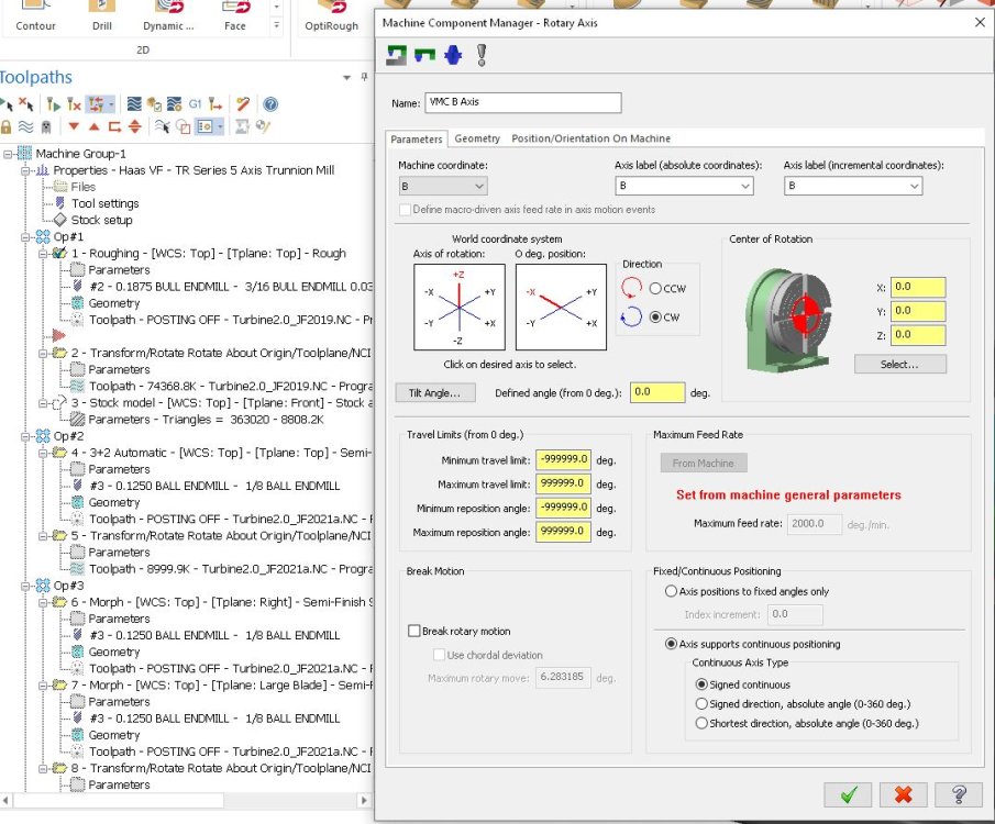
Ron is this with the Mi10 value? 0 = Continuous 1= Stay Positive 2 = Stay Negative
-
Not sure if this is a post issue or your Machine Definition limits for the axis. Did you check the Machine Definition?
-
It would have been an option most likely that wasn’t purchased.
-
Almost everything I have learned in Mastercam has been learned from reading topics on this forum and trying to figure things out (learning how). @Colin Gilchrist @crazy^millman have helped me a lot, I owe them many thanks!
-
Only the Rotary should be Inverse, leave the linear to Unit/min. You will need to set your Max inverse feed rates in your Machine Definition and possibly in the Post as well.
-
Your 4th axis Rotary is set to Degrees/min. I would use Inverse if you don't have TCPC on your machine to use Unit/min.
-
It depends on your machine and how Mastercam is set up (Machine and Control definition).
-
You shouldn't need to create a plane but without a file just guessing.
-
 Check out the free tutorials from In-House Solutions. https://www.inhousesolutions.com/resource/mastercam-2023-training-links/?fbclid=IwAR37BKhkMZ2SFG6_3x2l54fH-hdj9hCVQti4mQtgs0mPhoYu_uPEH1h_SYc
- 1 reply
-
- 4
-

-
Good band aid solution!!!!
-
Without a file it is hard to diagnose. Post a valid Mastercam file.
-
I would for simplicity like to have a block or blocks (gauge blocks or 1-2-3 blocks or a machined block) that is the exact height from the table to the center of the rotary. Then I can just probe that for the Z location each time. Then you can probe your tools. No math required.
-
Likely but double check by bringing the tool down to the Z0.0 and then set an Origin on the control. Then back up the radius of the part (in Z) and check your tool to the edge of the part.
-
Your Work coordinate (Z value) should be the Center line of the rotary. So if you send your tools to Z0.0 it should be the center of the rotary. Most Haas units are nominal 5" or 6" from the table to the center.
-
Your part centerline should be on the Axis center. Then you should be able to do an Axis Substitution with a Contour toolpath.
-
Flow 5 Axis will give you cutter comp.
-
By using additional and or sub toolpath groups to organize your toolpaths by operation type (roughing vs finishing) or cutter diameters or operation # or what ever makes sense. This allows you to isolate toolpaths easily. Then by having stock models in your process allows you to just process the selected toolpaths for verify. Make sure to use color loop in Verify, very helpful in finding where any gouges or problems are occurring.

