


4VRGJ03
-
Posts
51 -
Joined
-
Last visited
Content Type
Profiles
Forums
Downloads
Store
eMastercam Wiki
Blogs
Gallery
Events
Everything posted by 4VRGJ03
-

Question about Cut Parameters
4VRGJ03 replied to AppleUser347's topic in Machining, Tools, Cutting & Probing
C) Wear -
Cutting Internal Jarno Tapers
4VRGJ03 replied to 4VRGJ03's topic in Machining, Tools, Cutting & Probing
Alright gentlemen, So I figured this out.... I think. If you want to use a reamer you need to purchase a custom reamer for this job. According to my quote this will run you about $625US to about $825US each reamer. I have about 30 pieces to cut from titanium. Due to the size of the bore diameter you cant get the reamer in carbide at an efficient price. Which means how many titanium pieces can 1 reamer cut?? Because of this uncertainty and because of the risk associated with scrapping a block of titanium thats about 12" long 7.00" wide and 6.0" thick using a reamer, you need to grind this taper. The risk is lower and the price is about $350Canadian each piece with a non recurring charge for the fixture as well as the gauge used to check the part. A ball drop may work but your better off with a gauge that will sit flush to the end face when placed in the bore. If the taper is wrong the gauge will either sit too high or sink to deep. So the next time you have a fair size taper to cut in an expensive piece of material you may want to consider grinding it. Reaming titanium with this size and this type of taper is whey too risky. Before you master the reaming process you may scrap 1 or two pieces, and what if one of the flutes of the reamer you use chips off during reaming. Better to grind. In the long run it's cheaper and alot safer (providing the grinder knows what he is doing). This I Guarantee. -
Create holder from geometry, save holder only
4VRGJ03 replied to SlaveCam's topic in Industrial Forum
Or you could try this.....I posted this a few weeks ago I had the same issue and it was solved here...... https://www.emastercam.com/forums/topic/62476-problems-with-custom-tool-file-or-data/?tab=comments#comment-1222850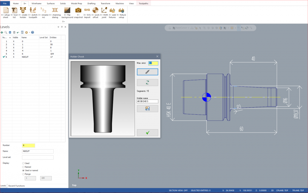
-
I recommend the Dell 7520 or the Dell 7720 I personally have the Dell 7520 with a Xeon E3-1505M v6 with 32GB of Ram and a 4GB Quadro M2200. Runs Mastercam and Solidworks very well. Pricey though. Purchased brand new off of Dell for $4600 including tax (Canadian) They come with a 3 year warranty. I already had a problem with the cooling system as the Fan's weren't working properly and Dell sent a technician to my house and the guy replaced the cooling unit in 30 min. So good customer service and good warranty but pricey. I use it everyday for 12 hours a day believe it or not. I like it because it's not a 17" full size laptop it's 15" with a full keyboard meaning it has the number pad on the side. 17" laptops with high specifications are big and heavy. I had a Dell M6800 and it was massive. The power supply alone was like a brick. But that laptop is still running today 9 hours a day and is virtually indestructible.. The power supply for the Dell 7520 is half the size of the M6800 but is still bulky, I stopped carrying around the power supply and just bought another off Dell. One I keep at home and the other I keep at the office. I find the 15" screen can be a bit small for Mastercam but I got used to it. I believe Dell makes the best mobile workstations on the planet. But you will pay.
-
Cutting Internal Jarno Tapers
4VRGJ03 replied to 4VRGJ03's topic in Machining, Tools, Cutting & Probing
Bingo! I didn't know they sold Jarno Reamers and your right I can check it with a spherical ball. Thank-you very much. I can now quote this job! -
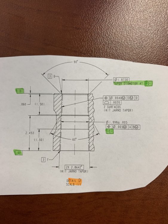
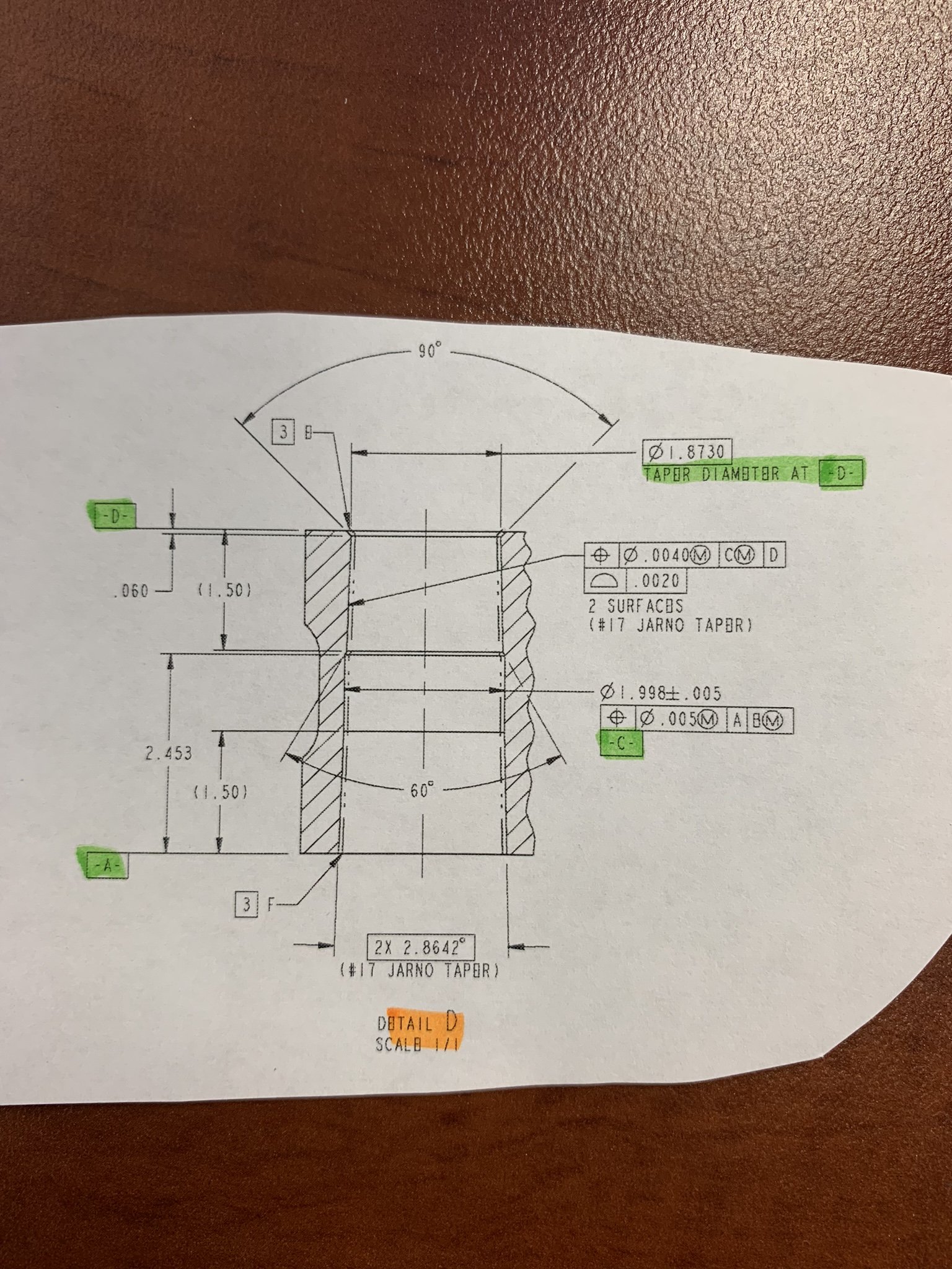
Good Afternoon Everyone! Does anyone have experience in producing an Internal Jarno Taper? I received a drawing which is calling out this taper on a hole. I have attached a piece of the drawing so everyone can see. I can't attach the whole drawing but the part itself is a fork like bracket and one of the cross holes has this taper. My question is how do I go about machining this taper? Is there a special tool? Does it have to be ground? Can it be turned? and finally how to check the taper? Do I have to buy a Gauges? I have a CMM but mabey I need a Go/No-Go Plug gauge? Not sure how to approach this. I appreciate everyone's time and efforts. The Material is Titanium
-
Thank-you jlw! That's exactly what I was missing. I didn't realize there was a contextual menu at the holder section which allowed the creation and saving of Tool Holders as well as libraries. Thats pretty decent of you. Thanks for your efforts. Perfect.
-
Hi Jlw. Thanks for your feedback. You are correct, the only question I have is how to export just the holder which I have created in Mastercam to a Tool Database so that it can be assembled with other tools within the Tool Manager Program. I am running Mastercam Version 2019. If you have that answer I would like to know and I appreciate your efforts on this. It's no biggie however because I now know the prerequisites for the DXF file so I can do it within the Tool Manager Program
-
Pitch in your little gems that make mcam life easier
4VRGJ03 replied to jlw™'s topic in Industrial Forum
I Recently came across a post which got locked because some kind of war started. People were trashing each other, throwing things at one another tossing tables and smashing chairs across everyones back but in the light of the fallout which looked like something of an aftermath of a RS-28 SARMAT ICBM, some thing good came out of that thread. Colin GilChrist (Which I nicknamed Mill-Christ due to his eapprentice lessons because this guy really knows his stuff on a level which I have never seen before) mentioned how to create new toolpath groups and subgroups and me being new to Mastercam I knew how to do this and understood the purpose of this but Colin showed a way that brought it to a whole new level. I am assuming that most people know this already but he showed the picture below. What struck me in this picture was the subgroups for specific operations.....ie; roughing, drilling, pocketing and so-on. I never thought to use toolpath groups like this before. I only used them to separate different operations. So in it;s simplest form.... the next time I'm drilling a series of holes I will create a group called Centre Drilling another group called drilling, and another group called tapping. The reason why this is recommended is that lets say I need to adjust the parameters for centre drilling I can find them easily as they are in their own group. Because of Colin's post my Mastercam files will never look the same again. Thanks Colin. I know most of you are saying..."well what did you thing the TOOLPATH group was for?? DUH!.thumb.PNG.940685ca1d8b3cccc2883a58e15a0baa.PNG)

-
This is a good idea to some extent. How did you build your holders? Did you build them within the Tool Manager Program or did you build them within Mastercam and then export them somehow to your ToolDatabase. "Somehow" is the key word. I don't know how to build a holder within Mastercam and save just the holder to a tool database that when opened with the Tool Manager Program it recognizes it as a Tool Holder. The only way I know how to do this is just to build the holder within the Tool Manager Program by importing a DXF file or by using the tool holder builder. The reasoning behind this is that I'm trying to standardize projection lengths so that operators and programmers don't use random projection lengths when building tools. If your using a 3/8 Endmill with a 1.00" flute length then the standard projection length would be either 1.500" or 1.375". It's all about automation. Automation works better when things are standardized.
-
Ok...I'm hesitating to post the reason due to my lack of knowledge in Mastercam, but here it goes...I could be wrong about this...but the real reason to create the tool in the Tool Manager program is because of the holder not the tool. However creating the holder in the Tool Manager Program follows the same process as creating the tool other than the fact that you place the holder on the NOCUT layer. I BELIEVE (based on limited experience) When you create a holder within the Mastercam interface the only way to get that holder into your library is to marry it up with a tool upon the creation of a toolpath and then export or "save" that "tool assembly" into the library by selecting the tool within the tool manager and right clicking the tool and selecting "Save to Library". Here is the issue with this....when you open that tool library in the Tool Manager program you will find the tool assembled with the holder in tool "Assemblies" I cant figure out a way to get the Holder into the "Holders Section" So that I can use the holder on different tools. Basically the holder is locked to that tool. By creating the holder within the Tool Manager Program I define it as a holder. That holder can now be "Assembled" with various tools. Someone can correct me if I'm missing something.
-
I'm confused as why this wouldn't be included in the "Tool Manager Getting Started" guide? Mabey that section is missing from my guide or mabey I just completely missed that section.
-
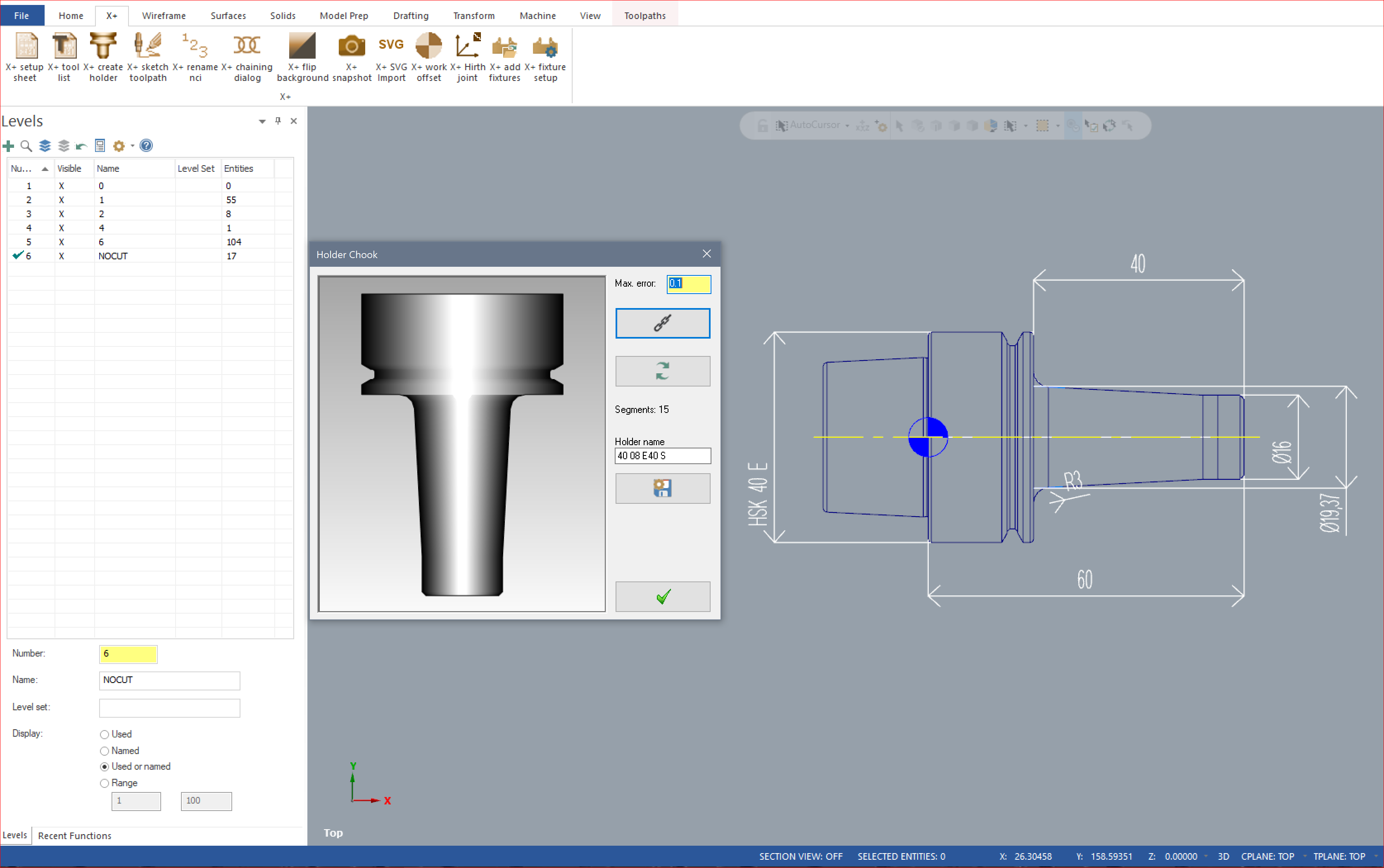
I just posted this on another thread but for someone who searches this and comes across this thread instead of the other one I'll post it here too. I would make a link to the other thread however I think these links get broken over time. Ok I figured this out. After 3 hours using every possible combination of geometry configuration. The idea is to create a custom tool using the only the Tool Manager Program and a DXF file. I have attached the Mastercam File which I used to create the DXF for eveyone's reference. The DXF MUST have the following attributes. 1 – 2 levels must be created and named as CUT and NOCUT 2- The geometry must be created on the upper left hand quadrant on the default TOP plane and on the CUT level 3- The length of the tool will be along the X axis (X-) and the diameter of the tool must be along the Y-axis (Y+) 4 – The tip of the tool must be placed at the origin 5 – The profile of the tool must be closed by a center line (ie. axis of rotation at Y Zero) Save the file as a DXF and load the DXF file and voila! There is a reason to doing it from the Tool Manager and not the Mastercam Interface which would take a while to explain. If anyone wants me to explain it let me know. My question is….where in any documentation does Mastercam tell me that this is required?? I have searched endlessly and could not find the prerequisites to what is required for the DXF file. DRILL.mcam
-
Ok I figured this out. After 3 hours using every possible combination of geometry configuration. The idea is to create a custom tool using the only the Tool Manager Program and a DXF file. I have attached the Mastercam File which I used to create the DXF for eveyone's reference. The DXF MUST have the following attributes. 1 – 2 levels must be created and named as CUT and NOCUT 2- The geometry must be created on the upper left hand quadrant on the default TOP plane and on the CUT level 3- The length of the tool will be along the X axis (X-) and the diameter of the tool must be along the Y-axis (Y+) 4 – The tip of the tool must be placed at the origin 5 – The profile of the tool must be closed by a center line (ie. axis of rotation at Y Zero) Save the file as a DXF and load the DXF file and voila! There is a reason to doing it from the Tool Manager and not the Mastercam Interface which would take a while to explain. If anyone wants me to explain it let me know. My question is….where in any documentation does Mastercam tell me that this is required?? I have searched endlessly and could not find the prerequisites to what is required for the DXF file. DRILL.mcam
-
Hi Jlw My reseller is In-House Solutions and they also built the post. I was also considering NCSimul over Vericut but I wasn't sure of the Price. I only have a quote from Vericut. Wow if NCSimul is 76% less than Vericut then I will definitely give them a call. So let's do some math here. Basically you are saying that NCSimul is about $6000 and to have Mastercam link the post to the Machine Sim is half of that which brings me to $3000. Either way I'll get my reseller to quote but I'm still not convinced that the simulation is as good as a third party verification software. I would like to see a demo before I purchase. Did I mention that setting up a single machine in Vericut is about $7000. (Be advised that when I speak I speak in Canadian funds) But here is the real kick in the face.....If you purchase a single platform seat from Vericut it will run you about $25,000. This is only good for one machine. If you decide to purchase another different machine in future you will have to upgrade your existing single platform seat to a multi-platform seat and if I understood the sales rep correctly the price is another $25,000. If you want to save money right of the bat you have to buy the Multi-platform seat the first time. Which I assume is close to $40,000. I only have a quote for a single platform seat. If NCSimul does the same thing for $6000 I'll buy two seats tomorrow
-
Alright I agree with some of you guys in terms of having "eye balls on the code" as you are right coffing up $25,000 for a single platform seat of Vericut isn't an option for some companies. But eye balling 5-axis code which is outputting a G68.2 (Euler Angles) to find the next plane is not something you can "eye ball" easily. Not having verification software means you are spending more time on the machine to de-bug. Eventually you may get better but it's when you become confident that the crashes happen. I asked my Mastercam reseller about this and he said that this is something that needs to be quoted which means you cannot simply "toggle" between NCI and NC when performing machine simulation in Mastercam. Bummer! Like I didn't spend enough on the software! But it would be nice to see how accurate the NC code simulation would be to the actual thing. Here is exactly what he said....... "With machine simulation we are able to create one for your needs that is as close to the the code as possible. This would need to be quoted" Notice the Key words here....close to the code as possible meaning its not perfect. Mabey Colin, (or anyone else) you could fill us in as to how accurate and how much better the Mastercam NC Machine simulation is over the NCI machine simulation.... In a nut shell is it worth the money??
-
Yes Mastercam Has the 5X linking command which will do exactly what you are asking....and all be well only if you have something to verify it with like Vericut. The Machine Simulation in Mastercam cannot be fully relied on. Do NOT fully rely on the Mastercam Machine Simulation for those types plane to plane motions. If you don't have something to Verify it with like Vericut don't even bother because what you are trying to do is where the catastrophic crashes occur.
-
Hi Guys I have open this up again because I'm trying to do the same thing that Roger was doing in this initial thread. The XML Tag "PROG-NUM" Does not produce a result. When I run the set-up sheet it continues to remain blank. I input the tag Correctly in the "Data Field". I have put in other XML tag with success but this one I can't seem to get it to work. Inputting the XML Tag "NCFILE-SHORT" recommended by "gms1" does not produce a result either. However his "Data Field" shown in his picture is actually "NCFILE/NCFILE-SHORT" and this outputs the NCI filename followed by .NC so my set-up sheet is reading "Fixture Plate OP40.nci.nc" So the question is How to Get the program number to output on the Set-up Sheet?
-
Ive drilled .033 holes in 43HrC 15-5PH Cres at 1.0"/Min feed 1200RPM and .008" peck using a carbide drill. The projection of the drill must be as small as you can. The depth was .245". But i'm new at this game. That worked for me. I need to ask the operator how many times he changed the drill during the job. I just know he didn't break any drills in the pieces because we are aerospace and everything thats scrapped is tagged.
-
Hey Guys, I'm going to throw this out there...has anybody noticed that running Machine simulation with Color Loop turned off actually speeds up the re-positioning of the axes during simulation? The issue is I'm running a 5-axis (trunnion table configuration MAZAK VC Smooth 5AX) program on machine simulation and when the color loop is turned on the machine pauses to reposition and takes a couple of seconds to properly reposition prior to starting the operation. The result is a broken simulation. However when Color Loop is turned off the reposition is super smooth with zero delay to the start of the operation. Color loop is a feature which I believe is important to identify which features or faces have been machined. I'd rather have it on. I believe my processor and graphics card are adequate enough (I7-4930K and Quadro P4000) Mabey someone has experienced this problem and mabey has a solution for this or some recommendation?? Thanks Guys
-
Good Evening Everyone. I'm going to throw this out there. Here is my issue. When I create a Set-up Sheet, Mastercam takes a current screen shot of the part and displays that screen shot on the first page of the Set-up Sheet. I like to add dimensions to this. The issue that I am having is that Mastercam creates dimensions Parallel to the current construction plane. So....Let say I have a rectangular block. The Length and the width of the block run on the "X" and "Y" (which is my current tool / construction plane) and the thickness runs on the "Z". I can create the dimensions for the Length and the width but I cannot create the dimension for the thickness. I have to create a plane parallel to the "Z" Axis and orient it so that it is normal to my intended view and create the dimension. The Question is....Is there any way to create the dimension along the thickness of the part without having to creating the plane? I would really like to see eMastercam have a thorough tutorial / E-Book strictly for Mastercam Dimensioning. Am I the only one who constantly hits the wall when dimensioning with Mastercam?? I hate looking through hours of video on the internet only to piece together small bits of information.
-
Ok, Ok, I see where this went.......I agree having 22 years experience by far takes the cake however think of certificates as ammunition which you bring to the table in an interview. I can talk till I'm blue in the face. But think about talking till your blue in the face and in the meantime slamming certificate after certificate on the table. Basically the certificate is like certifying what you say. The idea is to walk into an interview with the most amount of ammunition you can bring regardless of the company. By far experience is the best ammunition but the idea is to get the job so the more ammunition you bring to the table the better your chances. So basically If I have 22 years experience and I want to touch up my skills because I've used Hypermill for a long period of time and now I need to re-learn Mastercam X8 or X9 because I changed companies then no, paying the premium for the online course may not have been the most economical choice.... but If you are staring from scratch and will need to convince someone to give you a chance the certificate will definitely work in you favor. It might not land you a pay rate the same as the guy who has 22 years experience without any certificate, but it might help you get a seat. What you do when your in that seat is entirely up to you. But this is all just common sense.
-
I just completed the Mill Level 1 Course. Upon completion you can print the Certificate right away. I like what I received. It looks professional and authentic. I can only recommend that it is printed on a high quality colour printer and on card paper to ensure you get the maximum effect. I do not have a high quality printer therefore I will have to pay to get it printed. The certificate could have made reference to a unique certificate number to add to it's robustness however it does have the Mastercam Logo so regardless it will be recognized as legitimate within the industry. I very impressed with the content of the course as well as the certificate. It was definitely worth the money. I look forward to taking the rest of the e-courses. So to wrap it up...If you are looking to learn Mastercam and need something to show for it at the end which will be need to be recognized by the industry. Paying for the e-course will get you there. Great job guys.
-
I'm taking the Level 1 Mill course right now. I purchased all X8 courses. Cost me a little over $1200 Canadian. I will comment on them all as I will complete all of them thoroughly. In a nut shell the courses are identical to the corresponding training manuals. You could just purchase the training manuals and you will have exactly the same thing for a fraction of the cost. However purchasing the e-course gives you the certificate upon completion. This i guess would be the only reason why someone would pay the premium mark-up for the course. This is the only reason I paid $1200 for them. So my expectations will be high when it comes time to receive the certificate. The manuals come with the course as PDF files but are encrypted. This means that the manual needs to be unlocked when you use it. It requires you to enter your user name an password to unlock them. (I believe the unlocking requires that you have internet connection as it connects to emastercam.com to verify user name and password.) Adobe will give you the option of saving the password so it will unlock automatically the next time you open the file but it doesn't seem to work on my computer which is running windows 7. On windows 8.1 it seems to be working flawlessly. I except a nice looking certificate which looks legitimate. I will comment on the certificate when I finish Mill Level 1.

.PNG.b978e21490610326338ee4b5eb5f581d.PNG)
