Search the Community
Showing results for 'auger'.
-
Good Morning Everyone, I hope you all slept well. It's James Astles here and I am using a Quaser Fanuc oi-mf model and it has just thrown a too out. It has landed in the screw auger and got jammed. Any idea on how to reverse my screw auger thanks guys!
-
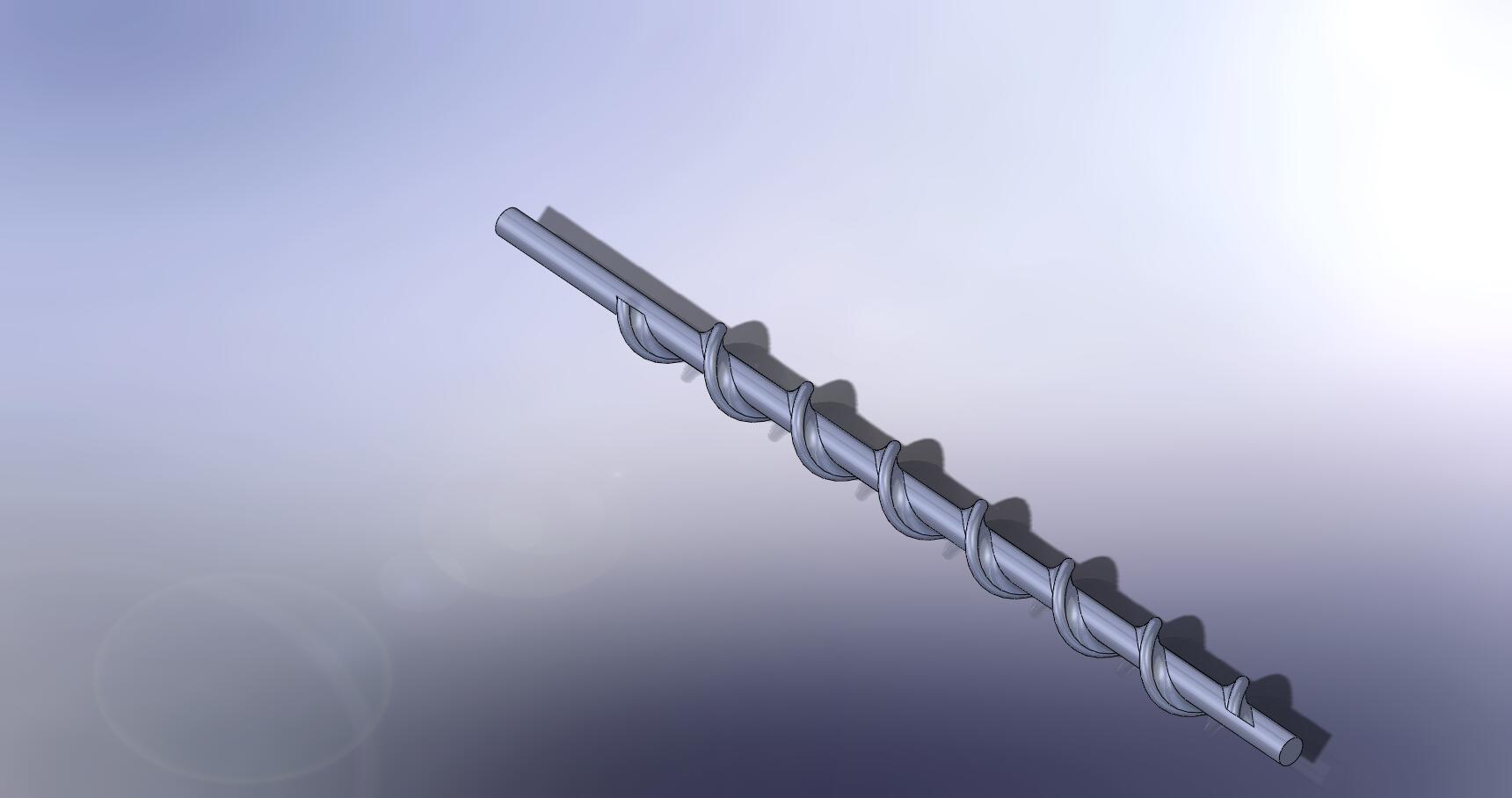
I am trying to cut this so I don't have to just run a 4th axis spiral path and add an offset surface to protect the o.d. I have had good luck with morph paths on other stuff but the curves aligned better. Is there anything someone can suggest on this? File attached thanks Label-Shaft-mill2.mcam
-
Normally there is a hex area on an auger to manually reverse them. Make sure all power is turned off before attempting this. Any injury or damage that may occur is not my responsibility and I assume not liability for offering this suggestion. Use this suggestion at your own risk. Best to reach out to the manufacture of the equipment and have them help you trouble shoot it.
-
Your on the right track and thank you for sharing your toolpath attempt. I unchecked the end surfaces. I changed the linking to use Cylinder. I also changed the cut type to Zig-Zag instead of spiral. I then changed the cut order from Outside to in. I extended your 2 curves to go past to allow the toolpaths something better to drive from verses the chopped out process you were getting. Still not giving me consistent cutting like I would want to see on a auger like this. Now I go extremely oldschool back to the V9 days of cutting augers. I draw my toolpath and drive it using Curve 5 axis. This will take you the better part of a day to complete, but I promise you will be hard pressed to find a toolpath in Mastercam that will cut as clean as this process. Here are the steps to reproduce what I put in the linked file for a couple areas. I made surfaces of the Auger Root using the solid from surfaces and the color mask picking those surfaces. I then created edges on a level using curve all edges. I then used create point segment to create 5 equal point on the top edges for each surface. I then used Create Flowline Constant Parameter to make the lines to give use the along lines in the middles of the surfaces. I then used create point segment again for 20 equal points on those 5 edges. I then used create manual spline with Auto Cursor Locked to Point to start creating the spline to drive the toolpath that will change as the tape changes to be an equal amount from start to end on the gradual change of this auger. I then used Curve 5 axis using the Splines created to drive the toolpath. I used 4 Axis as the Toolpath control picking the origin as the point for the rotation which aligned to the center of the auger. I used the surfaces to comp the toolpath to. I used a .200 shift in the tool control. I also defined a Safety zone that is 5" diameter around the part to give nice motion back and forth between cuts. Like I said a days worth of work to do the whole auger, but the toolpath and quality of the auger from it will be unsurpassed. Maybe there is a current toolpath able to match what this old school process does, but I still haven't figured out a way or had to time to keep seeing what would work like this does. 5th Axis Example
-
Hello, I'm trying to figure out how to rough out the helix of and Auger using HSM toolpaths. We keep getting more and more Augers that we need to make and our current strategy is extremely time consuming. First thing is, we do these on a Haas VF0 with 4th axis (HA5C which is a small full 4th) and simply do a X, Z, and A move do feed down along the Auger "flights" but take full width and shallow depth. My goal is to do more of a peel milling operation starting furthest away from the 4th axis and rough towards the 4th axis to maintain as much rigidity as possible while roughing. What would be the right toolpath to choose for this? Other details: The part is approx. 14" long with 3" major diameter and 1.5" minor diameter on large side and tapers to 1.25" major diameter and .38" minor diameter. The pitch is 1-1/4" and we turn a "blank" of finished OD dimensions before bringing it to the mill. When roughing with our current strategy we need to offset the tool off center in Y so that while the part is rotating the material is not coming up into the center of the bottom of the endmill. Staying on center in Y made terrible noises. We have MCX6 at the shop but I also have access to MCX9 at my other job both have multiaxis toolpaths.
-
Hi All, Whats the easiest way to put 3 equally spaced curves down the length of a spiral auger surface? Thanks
-
Here is one I did years ago for someone on the forum. I updated it to 2022 so you can what a consistent surface on the auger will yield when using Morph. 5th Axis Auger Example from Forum
-
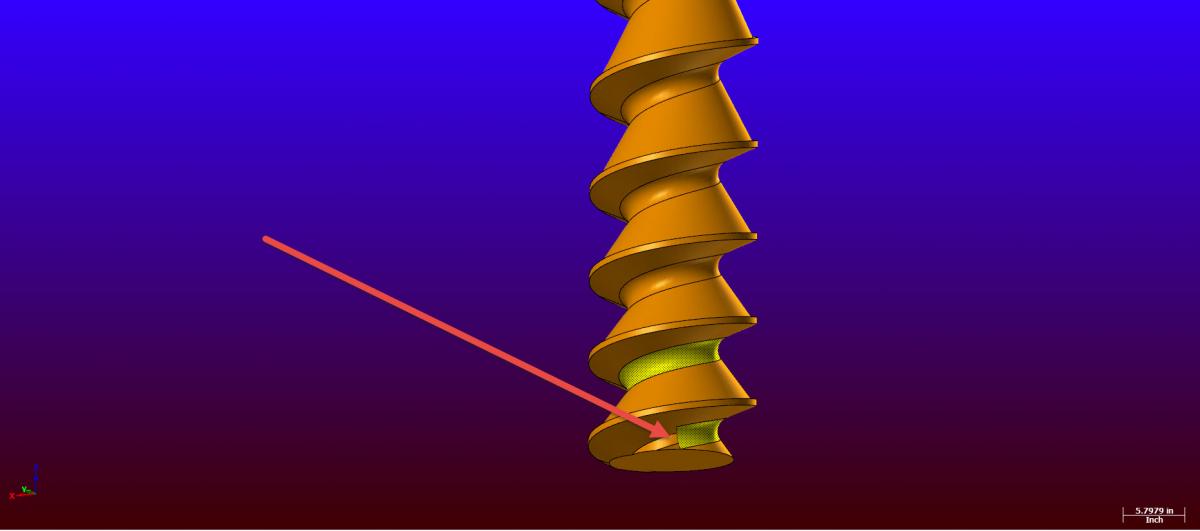
Hello Im having trouble getting a good toolpath on the auger. The blunt end of the thread is giving me fits. Depending on what I have tried it gouges or takes a heavy depth of cut or plunges into material. I saved the file on the ftp under unspecfied uploads folder (auger).IF someone wants to take a look and offer a suggestion . Thanks.
-
Hi Guys, I actually need help on a variable pitch auger, I cant seem to get to the roughing. I used a 4ax Swarf to finish the wall; but roughing has proven difficult. I'll upload it on the FTP under X5_files as MasaAuger.MCX-5. Thx !
-
Just looking for how you guys would tackle this part. I have axis to a 4ax haas. Part is about 14long and shaft diameter is .374 lobe diameter is .860. Material is s7 heat treated to 60rc when done. Just looks like a chattering pain to me. Any ideas would be appreciated. Gary http://www.emastercam.com/board/uploads/monthly_01_2011/post-735-0-97816000-1294236014_thumb.jpg
-
I want to add a M31 (Auger foward) to a parameter in Mastercam ... I want it on a switch. I've had difficulty with my canned text before... If I am roughing a chunk I want the auger on. If I go to a surface theres no need to run the auger for hours on end with no chips!
-
Does anyone know what the mcode is for turning the chip auger off on a Cinci750 w/ FANUC 21i? I can't find this in any of the documentation that I have. I have a warm-up program that I run each morning and the auger really doesn't need to be turning while the spindle is being exercised. TIA
-
Before I tear any further into this thing, anyone know where (and if) their is a clutch adjustment on a Haas auger? thx
-
Ok, were getting somwhere now... it only seems to work when placed here in the ptlchg0$ section as shown. Having it in pthchg$ makes no change code: ptlchg0$ #Call from NCI null tool change (tool number repeats) pcuttype pcom_moveb pcheckaxis !op_id$ c_mmlt$ #Multiple tool subprogram call comment$ pcan pbld, n$, sgplane, e$ pspindchng pbld, n$, scoolant, e$ if mi4$ = 1, n$, "M31" "(CHIP AUGER ON)", e$ #(added misc. int for auger 12/22/08) if mi1$ > one & workofs$ <> prv_workofs$, [ sav_absinc = absinc$ absinc$ = zero pbld, n$, sgabsinc, pwcs, pfxout, pfyout, pfzout, pfcou Now the wierd thing is, the M31 line comes on at every retract. I moved it all around that section, but it still comes on after every retract. code: G1 X-1.697 F50. G0 Z.25 ( ROUGH ARM ) S8000 M3 M31 (CHIP AUGER ON) X7.3883 Y-1.0752 Z.321 G1 Z.1286 F25. Y-5.7827 F50. Z.0363 F25. Y-1.0752 F50. Z-.0561 F25. Y-5.7827 F50. Z-.1485 F25. Y-1.0752 F50. Z-.2408 F25. Y-5.7827 F50. Z-.3332 F25. Y-1.0752 F50. Z-.4255 F25. Y-5.7827 F50. Z-.5179 F25. Y-1.0752 F50. Z-.6103 F25. Y-5.7827 F50. Z-.7026 F25. Y-1.0752 F50. Z-.795 F25. Y-5.7827 F50. G0 Z.25 Z.321 M31 (CHIP AUGER ON) X5.8883 Y-.6166 G1 Z.1286 F25. Y-5.2965 F50. Z.0363 F25. Y-.6166 F50. Z-.0561 F25. Y-5.2965 F50. Z-.1485 F25. Y-.6166 F50. Z-.2408 F25. Y-5.2965 F50. Z-.3332 F25. Y-.6166 F50. Z-.4255 F25. Y-5.2965 F50. Z-.5179 F25. Y-.6166 F50. Z-.6103 F25. Y-5.2965 F50. Z-.7026 F25. Y-.6166 F50. Z-.795 F25. Y-5.2965 F50. G0 Z.25 Z.321 M31 (CHIP AUGER ON) X4.3883 Y-.158 G1 Z.1286 F25. Y-4.8655 F50. Z.0363 F25. Y-.158 F50. Z-.0561 F25. Y-4.8655 F50. Z-.1485 F25. Y-.158 F50. Z-.2408 F25. Y-4.8655 F50. Z-.3332 F25. Y-.158 F50. Z-.4255 F25. Y-4.8655 F50. Z-.5179 F25. Y-.158 F50. Z-.6103 F25. Y-4.8655 F50. Z-.7026 F25. Y-.158 F50. Z-.795 F25. Y-4.8655 F50. G0 Z.25 Z.321 M31 (CHIP AUGER ON) X2.8883 Y.1 G1 Z.1286 F25. Y-4.4069 F50. Z.0363 F25. Y.1 F50. Z-.0561 F25. Y-4.4069 F50. Z-.1485 F25. Y.1 F50. Z-.2408 F25. Y-4.4069 F50. Z-.3332 F25. Y.1 F50. Z-.4255 F25. Y-4.4069 F50. Z-.5179 F25. Y.1 F50. Z-.6103 F25. Y-4.4069 F50. Z-.7026 F25. Y.1 F50. Z-.795 F25. Y-4.4069 F50. G0 Z.25 Z.321 M31 (CHIP AUGER ON) X1.6383 Y.1 G1 Z.1286 F25. Y-4.4 F50. Z.0363 F25. Y.1 F50. Z-.0561 F25. Y-4.4 F50. Z-.1485 F25. Y.1 F50. Z-.2408 F25. Y-4.4 F50. Z-.3332 F25. Y.1 F50. Z-.4255 F25. Y-4.4 F50. Z-.5179 F25. Y.1 F50. Z-.6103 F25. Y-4.4 F50. Z-.7026 F25. Y.1 F50. Z-.795 F25. Y-4.4 F50. G0 Z.25 M9 M5 G91 G28 Z0. M01 So close....
-
Can anybody tell me if I have the last 2 Misc Int's for my chip auger in the right place? I've moved them all around, but it still acts as if it's only in the psof$ code: psof$ #Start of file for non-zero tool number prv_tloffno$ = c9k pcuttype toolchng = one if ntools$ = one, [ #skip single tool outputs, stagetool must be on stagetool = m_one !next_tool$ ] pbld, n$, *smetric, e$ pbld, n$, *sgcode, *sgplane, scc0, sg49, sg80, *sgabsinc, e$ pbld, "G91 G28 Z0" #(added machine home 10/22/08) sav_absinc = absinc$ if mi1$ <= one, #Work coordinate system [` absinc$ = one pfbld, n$, sgabsinc, *sg28ref, "Z0.", e$ pfbld, n$, *sg28ref, "X0.", "Y0.", e$ pfbld, n$, sg92, *xh$, *yh$, *zh$, e$ absinc$ = sav_absinc ] pcom_moveb pcheckaxis c_mmlt$ #Multiple tool subprogram call # ptoolcomment marked out this line added it 4 Down to get tool comment on 1st tool change line comment$ pcan n$=t$ pbld, n$, *t$, sm06, ptoolcomment e$ pindex if mi1$ > one, absinc$ = zero pcan1, pbld, n$, *sgcode, *sgabsinc, pwcs, pfxout, pfyout, pfcout, *speed, *spindle, pgear, strcantext, e$ pbld, n$, sg43, *tlngno$, pfzout, pstagetool, e$ if mi4$ = 1, n$, "M31" "(CHIP AUGER ON)", e$ #(added misc. int for auger 12/22/08)<--------------------------- pbld, n$, scoolant, e$ absinc$ = sav_absinc pcom_movea toolchng = zero c_msng$ #Single tool subprogram call ptlchg0$ #Call from NCI null tool change (tool number repeats) pcuttype pcom_moveb pcheckaxis !op_id$ c_mmlt$ #Multiple tool subprogram call comment$ if mi4$ = 1, n$, "M31" "(CHIP AUGER ON)", e$ #(added misc. int for auger 12/22/08)<------------------------------ pcan pbld, n$, sgplane, e$ pspindchng pbld, n$, scoolant, e$ if mi1$ > one & workofs$ <> prv_workofs$, [ sav_absinc = absinc$ absinc$ = zero pbld, n$, sgabsinc, pwcs, pfxout, pfyout, pfzout, pfcout, e$ pe_inc_calc ps_inc_calc absinc$ = sav_absinc ] if cuttype = zero, ppos_cax_lin if gcode$ = one, plinout else, prapidout pcom_movea c_msng$ #Single tool subprogram call ptlchg$ #Tool change pcuttype toolchng = one if mi1$ = one, #Work coordinate system [ pfbld, n$, *sg28ref, "X0.", "Y0.", e$ pfbld, n$, sg92, *xh$, *yh$, *zh$, e$ ] if prog_stop = 1, pbld, n$, *sm01, e$ if prog_stop = 2, pbld, n$, *sm00, e$ pcom_moveb pcheckaxis c_mmlt$ #Multiple tool subprogram call # ptoolcomment Same as above, disabled this line added it 4 down to enable all tool comments comment$ #(comment before the N number 11/06/08) n$=t$ pbld, *n$, "G91 G28 Z0", e$ pbld, "G80 G49 G40 G20 G17", e$ pcan #comment$ #(placed comment between the T# and the N# 10/28/08) pbld, n$, *t$, sm06, ptoolcomment e$ if mi4$ = 1, n$, "M31" "(CHIP AUGER ON)", e$ #(added misc. int for auger 12/22/08)<------------------------------- pindex sav_absinc = absinc$ if mi1$ > one, absinc$ = zero pcan1, pbld, n$, *sgcode, *sgabsinc, pwcs, pfxout, pfyout, pfcout, *speed, *spindle, pgear, strcantext, e$ pbld, n$, sg43, *tlngno$, pfzout, pstagetool, e$ pbld, n$, scoolant,e$ #added following line JM 021209 pbld, n$, "/M8", e$ absinc$ = sav_absinc pcom_movea toolchng = zero c_msng$ #Single tool subprogram call
-
Hi there, A local user is trying to machine a variable pitch auger on a rotary (A) axis. From what I can see, it needs to use a 5 axis toolpath with 4 axis outut. He's got no experience with 5 axis toolpaths, and I have very limited experience, so I gave it a go for him. However, I can't get a decent toolpath. I'm sure its something I'm doing wrong, so would someone be able to have a look at the file and give me some feedback on how I should approach it? The file is on the FTP in the MC9 folder, and is called VARIABLE-PITCH-AUGER-TOOLPATH.MC9 Cheers, Mick
-
one more thing. You are missing a comma between the "M31" and "(Chip Auger on)". Change it to this. code: if mi4$ = one, n$, "M31", "(CHIP AUGER ON)", e$ #(added misc.int for auger 12/22/08) This could've also been written like this code: if mi4$ = one, n$, "M31 (CHIP AUGER ON)", e$ #(added misc.int for auger 12/22/08)
-
Master80, without spending alot of time going back over your model, I cannot get a solid fillet to work on your geometry, I can get a 1.36 to go all the way down to the last turn on the auger, but it wigs out and stops there. So the easy fix button here is just put a surface fillet on before you turn it into a solid.... It works just fine. I used a 1.36 also for the surface fillet but you can try a different size just start at 1.32 and keep increasing .01 until you get one to go... This is what I would have had to do if for some reason my solid fillet did not want to work either....Sometimes, no matter what you do or how hard you try to make something one way, it just will not work the way you want it to when working with solids...especially fillets...This is why, on complicated parts like this we go with surfaces and solidify it in the end. Nature of the beast... as a general rule, surface fillets will ALWAYS build easier than solid fillets....in ANY software package. You had so much leeway here this fillet was real easy...however if we were required to actually hold the 8" dia valley like the print, and called out valley radii, it would be an entirely different, complicated issue... There is one thing I would change though.... Each turn on this auger gets smaller to give it more power at the end and your last turn gets bigger... l would shorten it up more like the print...but that's just me I am picky. But since you appear to have wide open engineering leeway here, just rebuild your top and bottom surfaces so they extend above and below part so the fillet has enough room to extend past the trim lines so you get a full trim, rebuild your flat boundaries, and turn it into a solid again. Another reason why I extended my surfaces so far above and below.....method to the madness.... This is your model.

-
[canned text] 1. "CLEAN CHIPS - M00" 2. "CHANGE CLAMPS - M00" 3. "AUGER ON" 4. "AUGER OFF" 5. "ROTATE TO DEGREES" 6. "HOME MOVE - RETIGHTEN" 7. "AIR BLAST ON" 8. "AIR BLAST OFF" 9. "" 10. "" 11. ""
-
mic6, Are you getting any post erros? From the code you posted above, you should have been. It looks like you jammed the if statement for mi4$ right in the wrong spot breaking the logic for the if check of mi1$. when run, this should have produced some errors. using the code from the above post Change from this code: ptlchg$ #Tool change pcuttype toolchng = one if mi1$ = one, #Work coordinate system if mi4$ = one, n$, "M31" "(CHIP AUGER ON)", e$ #(added misc. int for auger 12/22/08) [ pfbld, n$, *sg28ref, "X0.", "Y0.", e$ pfbld, n$, sg92, *xh$, *yh$, *zh$, e$ ] if prog_stop = 1, pbld, n$, *sm01, e$ to this code: ptlchg$ #Tool change pcuttype toolchng = one if mi4$ = one, n$, "M31" "(CHIP AUGER ON)", e$ #(added misc.int for auger 12/22/08) if mi1$ = one, #Work coordinate system [ pfbld, n$, *sg28ref, "X0.", "Y0.", e$ pfbld, n$, sg92, *xh$, *yh$, *zh$, e$ ] if prog_stop = 1, pbld, n$, *sm01, e$
-
Well, I tried placing my Misc. Int right under neath the ptoolchange$ where Misc. Int 1 is placed, but it still won't post my M31 when I want to use it on something other than the first operation. Any other ideas? code: ptlchg0$ #Call from NCI null tool change (tool number repeats) pcuttype pcom_moveb pcheckaxis !op_id$ c_mmlt$ #Multiple tool subprogram call if mi4$ = one, n$, "M31" "(CHIP AUGER ON)", e$ #(added misc. int for auger 12/22/08) comment$ pcan pbld, n$, sgplane, e$ pspindchng pbld, n$, scoolant, e$ if mi1$ > one & workofs$ <> prv_workofs$, [ sav_absinc = absinc$ absinc$ = zero pbld, n$, sgabsinc, pwcs, pfxout, pfyout, pfzout, pfcout, e$ pe_inc_calc ps_inc_calc absinc$ = sav_absinc ] if cuttype = zero, ppos_cax_lin if gcode$ = one, plinout else, prapidout pcom_movea c_msng$ #Single tool subprogram call ptlchg$ #Tool change pcuttype toolchng = one if mi1$ = one, #Work coordinate system if mi4$ = one, n$, "M31" "(CHIP AUGER ON)", e$ #(added misc. int for auger 12/22/08) [ pfbld, n$, *sg28ref, "X0.", "Y0.", e$ pfbld, n$, sg92, *xh$, *yh$, *zh$, e$ ] if prog_stop = 1, pbld, n$, *sm01, e$
-
they have been covered before did you try searching? https://www.emastercam.com/search/?type=all&q=auger
-
One finishing toolpath for an auger of that nature? Good luck and I have cut many augers and when you achieve that Holy Grail toolpath then please share it.
-
sorry .I have one auger for machining on indexer .I want to use only finish toolpath .On this file I can mark floor for machining separately and 2 wings separately .But I want to remake the floor for split 2 half and machining the parts with half floor and machine side wing and half floor and operator side wing .
-
Whoa man that took a while to get back to this. Thanks for "waitin" Doug. All I did was find all the misc integers and copied the format to get the text to show up. code: -------------------------------- # Misc. Values: # -------------------------------------------------------------------------- # Integers: # # mi1 - Work coordinate system # 0 = Reference return is generated and G92 with the # X, Y and Z home positions at file head. # 1 = Reference return is generated and G92 with the # X, Y and Z home positions at each tool. # 2 = WCS of G54, G55.... based on Mastercam settings. # # mi2 - Absolute or Incremental positioning at top level # 0 = absolute # 1 = incremental # # mi3 - Select G28 or G30 reference point return. # 0 = G28, 1 = G30 # # mi4 - Chip Auger # 1 = M31 # # SPACE --------------------------- SPACE # Default Miscellaneous Integer Values - Read during post update only - Set in CD # -------------------------------------------------------------------------- 301. Work Coordinates [0-1=G92, 2=G54's] (mi1)? 2 302. Absolute or Incremental [0=ABS, 1=INC] (mi2)? 0 303. Reference Return [0=G28, 1=G30] (mi3)? 0 304. Chip Auger [1=M31] (mi4)? 0 # SPACE --------------------------------- SPACE # POST TEXT # -------------------------------------------------------------------------- [CTRL_MILL|GENERIC HAAS 4X MILL] [misc integers] 1. "Work Coordinates [0-1=G92, 2=G54's]"//2 2. "Absolute/Incremental, top level [0=ABS, 1=INC]" 3. "Reference Return [0=G28, 1=G30]" 4. "Chip Auger [1=M31]" SPACE-------------------------------------SPACE [CTRL_MILL|DEFAULT] [misc integers] 1. "Work Coordinates [0-1=G92, 2=G54's]"//2 2. "Absolute/Incremental, top level [0=ABS, 1=INC]" 3. "Reference Return [0=G28, 1=G30]" 4. "Chip Auger [1=M31]" ------------------------------------------------ So whuddya make of that?