


rgrin
-
Posts
112 -
Joined
-
Last visited
-
Days Won
1
Content Type
Profiles
Forums
Downloads
Store
eMastercam Wiki
Blogs
Gallery
Events
Everything posted by rgrin
-
I get it. Do as much as you can on the software side to reduce the amount you have to do at the machine. I don't have experience running Productivity+ so unfortunately I can't be of too much more help. Does it generate as a toolpath in the toolpath manager? If so, you could put a manual entry after the probing routine with your necessary G10 line so that way it atleast can post out correctly each time.
-
Am I correct in assuming that this custom macro puts those points into their own macro variables? If so, you can just use a G91 G10 Z#whatever line to do an incremental shift or if it is giving you the actual machine position you can do G90 G10 Z#whatever
-
I'm confused, why can't you run programs straight from the data server? I just switch my foreground and background folder to dataserver and I can run whatever I want without using a sub program call. This on a 2019 Yasda with a pallet changer and Fanuc 31i-B5 with IHMI. I know the older PX30i has to use sub program calls, but that is a software issue on the pallet changer side that the scheduler could not pull programs from the data server when it was in unattended mode. The newer Yasda has better software and can pull straight from the dataserver as long as your foreground and background folders are set to dataserver.
-
The shop I work at, every machinist is their own programmer. The vast majority have 1 program per file and separate the setup flips into their own file. They also don't use toolpath groups. You can find programs with 100+ operations and it can be a pain to go thru them if you need to make a change. I'm fortunate that I have essentially been separated from the rest of the company when I was put in charge of our pallet changer. While I see the argument that I should have continued doing what everyone else did, I just disagreed with it since IMO for the work I do now that using groups, viewsheets, and organized levels really helps me make efficient programs. I just need to settle in on exactly what I want to do now and stick with it...
-
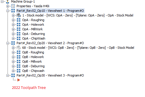
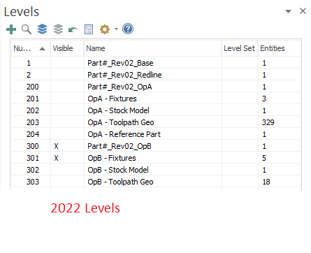
Currently I am running 2022 but today is the day I make the switch to 2024. I am in the process of overhauling the main part family that my machine runs and with that I am trying to nail down how I want my programs to look. I started programming full time 3 years ago and I have grown and learned a lot since then. But it is time for me to clean up my act and I would like your guy's opinions on how files should look. In 2022, I run my parts thru 1 machine group, then have a Base toolpath group for each Op/ Part setup. With in that tool path group, I break up into sub groups depending on what I am doing. (roughing, finishing, drilling) I utilize viewsheets to allow me to flip quickly thru each setup. I like doing it this way since it helps me make changes if I need to. It also means that I have only 1 tool manager library for an entire part which makes global changes to tools a lot easier. With the changes to machine group setup in 2024, it allows you to assign part model, stock model, and fixture models. At face value, I like that change. It jives well with how I structure my program and so far has eliminated my simulator errors when assigning stock models and fixtures. However, in order to fully utilize this you basically would want to have a new machine group for every new setup in order to assign the correct stock model and fixturing for each setup. The major drawback to this is that now you will have multiple independent tool libraries for every machine group and this will make managing tools more cumbersome between each program. How are you folks handling this? Browsing previous posts about this subject, it seems quite a few are basically using the same method I am currently in 2022. Are any of you utilizing the new machine groups fully yet? Or is it another implementation that ain't quite there yet?
-
Figured I would come back to this with an update in case it helps anyone in the future. Finishing up running the last 2 parts tonight out of my order of 60. Successfully made all of them to the flatness spec, but ended up not needing a grind op at all. The process we settled on was to bake the stock, rough both sides, cryo treat it, and then finish both sides. I was able to machine to better than .0002" flat over 98% of the part and the other 2% crept close to .0003"-.0004" but fortunately it was in a spot that customer was ok with that. The cryo treatment takes the parts to -200F for 3 hours and then throws them in an oil bath at 200F for 3 hours. This seems to have solved our warping issue as previously my parts were coming back at .0005"-.0007" flat from plating and now with the cryo, we are maintaining .0002" flat over 98% of the surface. I never got the chance to try and grind the anodize since we were able to use a manual process to straighten the more warped ones back into spec. The finishing fixture supported the part on 3 pads and clamped on 2 pads on the longest dimension of it. I used 2 pitbull clamps torqued to 5 in/lb to force the part to sit on 2 of the pads. Attached is file with the fixture I used and mock part. Flatness Fixture.mcam
-
Does anyone use sandvik 460 drills?
rgrin replied to Leon82's topic in Machining, Tools, Cutting & Probing
+1 on lowering the ipr a bit. Didn't realize he was at .00475" ipr and thats a tad more aggressive than I would do. Also, +1 on the GOdrills as far as tool life goes. I didn't check them for position, but I drilled ~600 holes with a 5/16" one about 1" deep in 4140 at 38rc and that tool is still in the machine looking minty. Finally a Kennametal product I like -
Does anyone use sandvik 460 drills?
rgrin replied to Leon82's topic in Machining, Tools, Cutting & Probing
No personal experience, but it looks like its just a plain jane single margin drill advertised as a "do it all" drill. My experience with "do it all" tools is that they can do it all, but usually not as well as a more specific tool would. A double margin drill would typically yield better straightness, but have problems if you aren't breaking a chip. What is your definition of walked pretty bad? Maybe consider spotting it first if you can? -
Haas probe for flatness in Z axis
rgrin replied to david's topic in Machining, Tools, Cutting & Probing
I just realized the easy way to make Colin and David's work. (Maybe it was obvious to them/others but it just dawned on me). I would use a separate work offset for checking the part. So if you're machining in G54, I would check it in G59 or something. After machining is complete, I would call the probe up and reset G59 to the top of the part and probe it and set the current value of G59 offset. THEN you could use the H.001 tolerance to see if all subsequent probe points are within whatever spec you want. Seems so simple now.... -
Haas probe for flatness in Z axis
rgrin replied to david's topic in Machining, Tools, Cutting & Probing
I think the issue with that is it would effectively mean he needs to control his z-axis position to +/-.0005" for that check to work. If the part doesn't require it already, that shoots the difficulty level of making that part way up IMO. So either you have the challenge of maintaining z-axis height part to part to +/-.0005" and have to make sure you control it to the same point every time you set it up. OR you do the work and write the macro logic and save yourself the headache for the future. If it's going to be a repeat part, I would lean towards writing the logic personally. -
Haas probe for flatness in Z axis
rgrin replied to david's topic in Machining, Tools, Cutting & Probing
I can picture what you want but I can't think through how you would have to write the macro. I think you would have to store each point as their own variable since you're baked in routine will just overwrite each one into the same variable. For instance, my machine is set to write my probe points to #108 so after each probe point you would have to write #500 = [#108] and change the #500 variable for each probe point. That will give you an array of as many points as you want. The hard part that I haven't figured out yet is how to parse thru those variables. You would need to find the one with least deviation and the one with the most deviation and then subtract their values from eachother to see if their relative deviation is more than .001". Brute forcing to find you min/max deviation is not hard, but the only way I can think is test each one against eachother with LT (Less than) or GT (Greater than) statements and that will be extremely cumbersome to write. Hopefully someone more MACRO B inclined will chime in as this is something I have wanted for awhile for some process inspection, but just haven't needed enough to justify the time spent yet -
Too true about the cost savings preventing a crash. it just seems odd that Mastercam Mach Sim doesn't seem to get pushed too hard. The typical answer I see is just get Camplete, Vericut, or NCSimul. Seems odd since what I have seen is that Mastercam would cover pretty much all of my bases and inside of 1 package.
-
We use camplete for our post and mach sim for our 5-axis machines. I don't think we ever fully utilized it and the implementations have been half-baked at best. I've been wondering ever since AutoDesk bought camplete if it was worth continuing our relationship with them. My biggest concern is long term support for the camplete plug in. Is the mach sim in Mastercam on par with these other options yet? I know in order for it to mean anything, you need to have them designed around your post. My ideal scenario is using just Mastercam since it gets annoying managing multiple licenses to other vendors. I had a quote from our reseller that it would be ~$4500 to get started on the Mastercam Mach Sim. To me that seems reasonable since I think our AutoDesk subscription is like ~1k per year per seat or something like that. The other question I had but never got answered was how much hassle is it to keep that Mach Sim up to date every Mastercam release. Are there any potential new bugs I would run into?
-
I agree with Kyle F in that I don't see slot mill used very often. Typically for a feature like that if tool is close to the size, I would use a 2D Contour set to Ramp it since it would be gentler on the tool. Otherwise a 2D Dynamic with a helix ramp in to rough it and a 2D Pocket to finish it. Just a few ways to skin this cat.
-
You have too much stock to leave on walls I bet. Looked like .05" on walls and .05" on floor...
-
I'm also pretty certain that setting step up as the same as your step down will make it so it only machines all the flat areas on that plane. It seems odd that that is how you sometimes have to do it. It might nice if they had a "Critical Depths" option similar to 3D Waterline. I remember when I first started using optirough and having a hard time getting it to machine all the flats I wanted.
-
Multiaxis pocket I assume still supports them. Heres a video from the Mastercam youtube page showing it. https://www.youtube.com/watch?v=T1YwR45pbLA I know I saw another video there that showed them using a taper form cutter to finish a wall. Almost certain it also used Multi axis pocket
-
Reducing code within 3D surface finish flowline?
rgrin replied to brussell's topic in Industrial Forum
Why use 3d at all? Perfect application for 2d Swept. The 2d toolpaths in my experience give the cleanest motion with least input and code. It also looks like you're doing a spiral toolpath which is probably gonna require alot more code as opposed to one way. -
I don't have a millturn environment, but I am able to backplot your toolpath it seems. Any particular reason you're using a bullnose endmill as opposed to a ball endmill? Traditionally I have seen people finishing the blades with a taper necked ball and the current hotness is the fancy form cutters. Another thing too is it looks like you're feeding the tool at 3000mm/min? That converts to like 120 inches per minute for my American brain. That seems awfully quick, especially since it looks like you are zigzagging. I would say the toolpath look fairly normal other than the quirky retracts at the edge of the blade on the first paths. I would personally try and get the toolpath to wrap around the blade in 1 motion so that way you are climb cutting the whole way down. Switching to a ball will give you a larger radius you're cutting on and give you fewer scallops than your bull nose. I would personally use the toolpath with the most points and then mess with any smoothing settings on the cnc control to get the finish I want.
-
Are you still rocking a Logi G602? Hands down my favorite mouse I ever owned, but mine developed that goofy middle mouse button problem. I was going thru some drawers and I found my old one and am thinking to try and fix it. I also saw newegg claims to have new ones for $90. Tempted to get one. It just fit my hand perfectly and the material feels nice.
-
I am using Loctite 425. The best way I have found is when you are done machining, you pop the part off the fixture and let it sit in open air for a day and it just flakes right off. My cycle time is such that it runs for about 8 hours and then before I leave I pop all the parts off and blow the coolant off and set them on the table. Then I scrape it all off with a plastic piece I cut up. If you need a faster turn around, acetone works but it can leave a gummy residue. So, it requires a once over after the initial cleaning. They also sell a solvent but I haven't used any and I can't recall what it's called. All in all, I do not recommend glue as a production process. It is quite cumbersome and is prone to failure if left in the machine/exposed to coolant for too long.
-
We actually have blue photon at our other facility that we use for the tricky to hold aerospace prototype parts. I'm keeping that one in my back pocket as last resort. I would prefer a method that uses mechanical means to work hold. For instance with the super glue process I am running right now on a different part, I have 5 ops that utilize it. It takes me about an hour to get all ops glued up and then cure for another hour. On the smaller batches I am running right now, that's fine. But this new project that I am being put in charge of, I need to yield start to finish 10 parts a week for the next 3 months. If I have to wait/setup 15 - 30 minutes for my workholding, it will kill me and my deadline. There are holes in it and I intend to use them with expanding mandrels. My first op will be to rough/finish a bunch of lightening pockets on the backside and drill all the non critical holes. Then my 2nd op I will use expanding pins to secure/float it with hopefully minimal twist and remachine the periphery. Then it gets stress relieved and I remachine the flat surfaces again on both sides. The goal is to get .0005" flatness Pre plate and then remachine the plating to .0002" in a vertical mill with the grinding wheel I mentioned. The concern with going above .0005" flat is that you will see discoloration since the anodized gets dyed black and it starts to look bad as you machine the unevenness out of it
-
So I dug a bit deeper. Kaiser Select 6061 is in a T651 state which is almost the same as T6511. They get the same stress relieving, but T6511 gets a straightening operation. Talking to our shop owner, his past experience is that the difference between the two has proven to be negligible once you get down to this extreme of tolerance. So with that said, my current course of action is to design up fixturing that isn't reliant on super glue for flatness. That way I can start running them in our pallet changer and get our efficiency back up on the front end. In the mean time, for the ones that have already been made and need Post Plate Processing, I found a CBN bottom grinding mandrel from a company called Di-Coat. $60 for a 1/2" diameter wheel seems like a no brainer easy way to at-least start testing grinding in one of our verticals that is currently idle. Thanks for all the suggestions!
-
Cast is probably out. The part has been approved for production since 2020 with 6061 being specced by the customer. They can be a pain to get changes through and most of the time asking fewer questions is just easier. I looked at the print again and to my surprise they don't specify what temper of 6061 they want. So maybe we could look into that? Also, thanks for telling me it's a cold process. I'm pretty new to this anodize stuff since I only deal with it pre-plating. Now that they got me going after it post plating I am trying to find as much info as I can. I just recall (probably incorrectly) that when I first started here that someone told me we bake our parts since it helps stabilize them prior to anodize and that the temp we ran at was similar to the anodize process.
-
That could be, The process is we do a heat stress relieve prior to machining. Then we rough the parts and re-stress relieve prior to finish machining and then they go to plating. The material is 6061-T6 Kaiser Select, so it should be fairly stable at that point. But sometimes ya just never know. I believe the temperature we stress relieve to is around the temp of the hard anodize process. So we aren't removing any temper but we also kind of simulate the anodize process as far as the heat is concerned.

