Greg Williams
-
Posts
2,221 -
Joined
-
Last visited
-
Days Won
3
Content Type
Profiles
Forums
Downloads
Store
eMastercam Wiki
Blogs
Gallery
Events
Everything posted by Greg Williams
-
I dont think it can create reverse angles like that, you may have to draw it old school
-
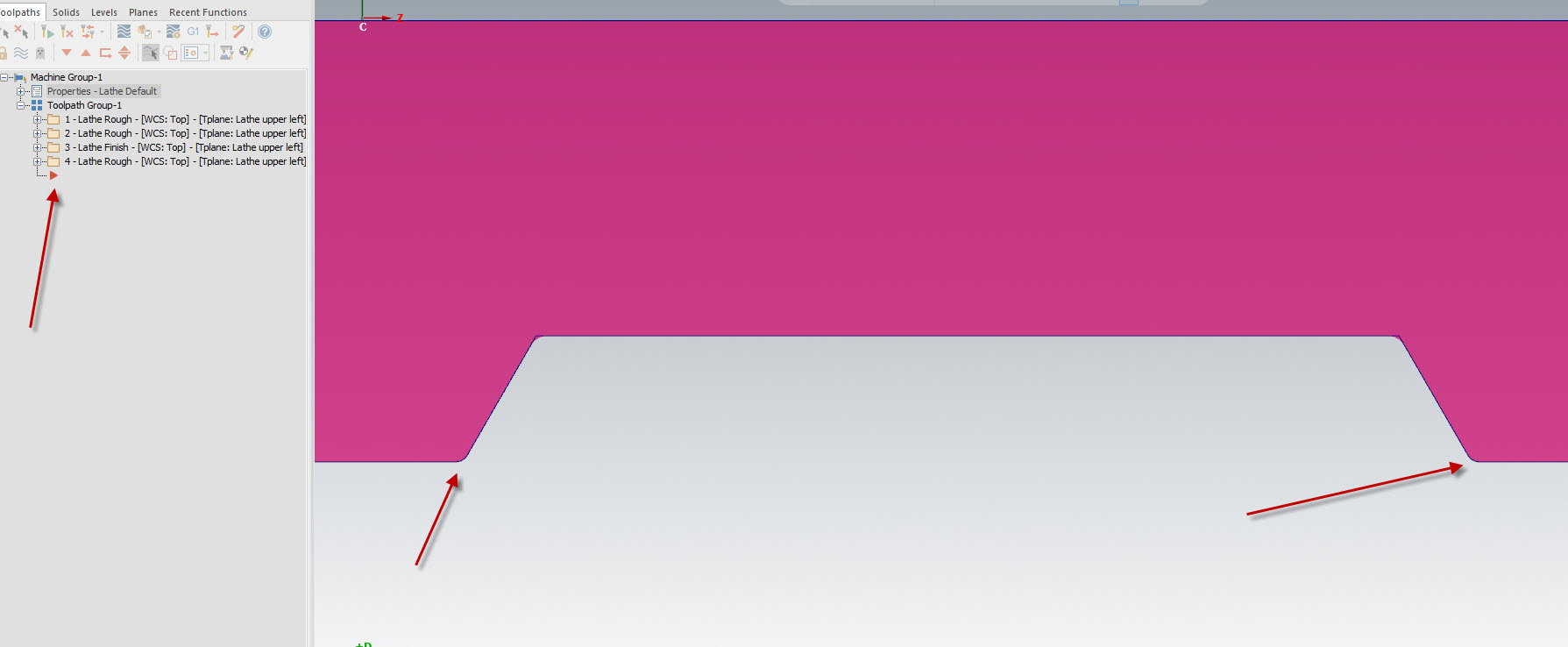
Lathe toolpath not symmetric with reversed chain
Greg Williams replied to Azoth's topic in Industrial Forum
The file looks okay here, where is your operation arrow?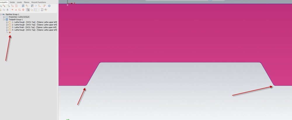
-
I have played with a few of these, are you using the DMG structure or running the MPF file?
-
Fanuc 5 Axis Parameters
Greg Williams replied to Cage86's topic in Machining, Tools, Cutting & Probing
Thanks for posting James, very useful info -
n_tpln_mch - what is its possible values?
Greg Williams replied to Giang-TT's topic in Post Processor Development Forum
If the G68.2 block spins the C axis table to a different place to what the Gcode is expecting the program will not cut the part correctly. Try my sample part of a machine and you will see the problem. -
n_tpln_mch - what is its possible values?
Greg Williams replied to Giang-TT's topic in Post Processor Development Forum
- With my simple approach, I used the toolplane vectors to get the i,J,K value directly. With this method, my tilted plane's X&Y may not align with the machine X,Y axis after applying the G68.2 (e.g. X100. command will cause both X and Y axis to move) ------------------------------------------------------------------------------------------------------------- Yes this is the problem with using the plane, we need to use the operations X axis - With your method, the tool plane's X&Y axis will be rotated to align with the machine XY axis after applying G68.2 . Am I correct? ----------------------------------------------------------------------------------------------------------------- Yes correct Your code is correct to calculate the Euler angle from the plane, but using the plane is not the answer. -
n_tpln_mch - what is its possible values?
Greg Williams replied to Giang-TT's topic in Post Processor Development Forum
YOu will need to add the code to transition from 3+2 to 5 axis and back again. You can cycle it back through p_goto_strt_ntl or create a new block -
n_tpln_mch - what is its possible values?
Greg Williams replied to Giang-TT's topic in Post Processor Development Forum
Hi Giang, If you use s_out and p_out to calculate G68.2 you will always get the correct result. if you use the plane you will not always get the correct result. If you use mi10 to flip the solution you will not get the correct result unless you flip the plane as well. Post ops 10 and 11, they should give you exactly the same gcode. T19 M6 G0 G54 G90 A-23. C180. G68.2 X0. Y0. Z0. I180. J-23. K0. G53.1 M38 M10 X0. Y-51.7542 S1800 M3 Op 12 is the same but the solution has been flipped with mi10, so hence the Y axis values are now inverted. G0 G54 G90 A23. C0. G68.2 X0. Y0. Z0. I0. J23. K0. G53.1 M38 M10 X0. Y51.7542 S1800 M3 Euler Angles.mcam -
n_tpln_mch - what is its possible values?
Greg Williams replied to Giang-TT's topic in Post Processor Development Forum
Giang, If you use m1$ to m9$ the plane will need to have the correct orientation, if the plane is not correct to the final machine orientation then the code will be different to what the G68.2 block is outputting. Post ops 8 and 9 of the attached file, you will see if your calculation is correct, both ops should give the same G68.2 IJK angles. G68.2 X0. Y0. Z0. I180. J-23. K0. If your machine is XYZAC you already have the 2 correct angles, if you have XYZBC or XYZAB then you will need to run the calculation or create a matrix and rotate the 2 angles you have back to AC orientation. Euler Angles.mcam -
Your Content file is empty.
-
Uploading a sample file will be best
-
n_tpln_mch - what is its possible values?
Greg Williams replied to Giang-TT's topic in Post Processor Development Forum
Giang, This can be done, For the G68.2 block I would use 2 angles not 3. If you want to use 3 angles you will need to create the Euler maths in a post block. If you create the maths use the new recalculated X axis vector from inside the post. If you use the toolplane to calculate the 3 angles the X axis may come out incorrect depending on how the tool plane has been created. Also you will need to write a block to handle the transition from 3+2 world to 5 with TCP on and 5 with TCP on back to 3+2 world with the same tool, currently there is no solution for that in the generic 5 axis post for this senario. Top Map will only output 1 or 2 off G68 blocks which will rotate the Gcode but on most machines I have seen the G68 will not datum track the rotations. For this we need G68.2 I have not used n_tpln_mch for any calcs but further down the string is mentioned and commented n_tpln_mch : -2 #Nutating machine selection when toolplane output I dont know who originally wrote the Generic 5 axis post but full respect to them as it is quite a document. -
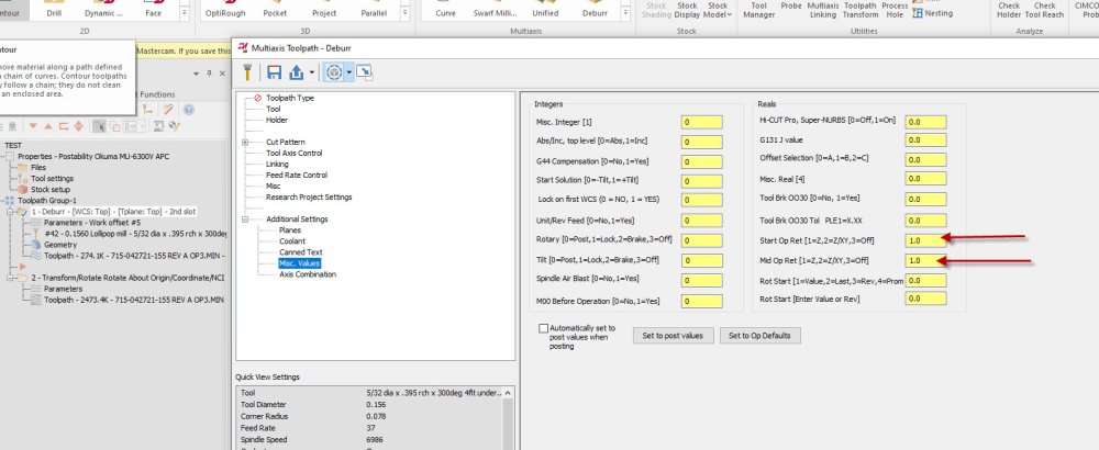
You could just change the Misc reals to 1 here. The code looks okay then
-
I get the same error, the code should be something like this at the transform. You will need ot contact postability through your dealer X2.33101 Y-8.36638 Z-4.6949 X2.3322 Y-8.36249 Z-4.68972 X2.3325 Y-8.35994 Z-4.68376 A-15.8438 G00 X2.33094 Y-8.34638 Z-4.63566 X2.27008 Y-7.81749 Z-2.75974 Z9. (2ND SLOT) X1.75446 Y-7.70568 Z9. A0. C0. Z-3.36978 Z-5.31978 G01 Z-5.36978 F10. X1.75506 Y-7.70555 Z-5.37745 F37. X1.75678 Y-7.70518 Z-5.385 X1.75945 Y-7.7046 Z-5.39237
-
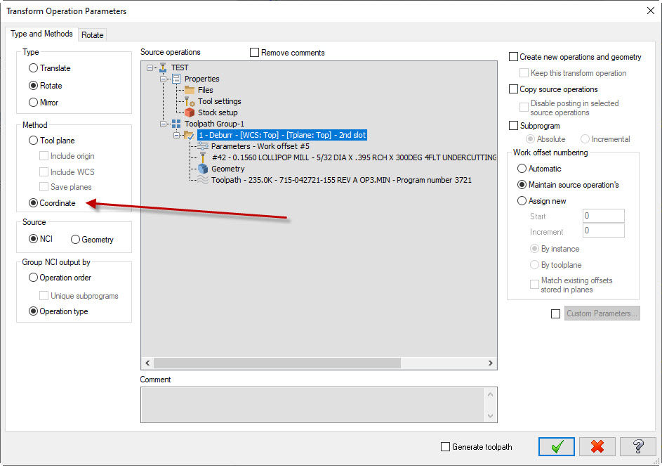
To transform 5 axis ops you should use coordinate not toolplane
-
I would use G469 G30 P1 (16 ENDMILL R0.5 4FL |TOOL - 16|DIA. OFF. - 16|LEN. - 16|TOOL DIA. - 16.) G116 T16(16 ENDMILL R0.5 4FL TOOL - 16) G0 G16 H0 Z999. M01 G15 H1 G469 P1 Q313 X0. Y0. Z0. I0. J-45. K0. G467 P1 G0 G90 A-45. C0. S1790 M3 G0 X16. Y-31.074 Z999. G56 HA Z75.064 G468 P1 M510 (CAS OFF) G169 HA G0 X16. Y31.106 Z75.05 A-45. C0. G131 J2 E=0.025 D=0.015 I0 F20000. (SUPER NURBS SEMI FINISHING) Y-33.544 Z10.4 Y-40.616 Z3.329 G1 Y-47.687 Z-3.742 F600. X15.998 Y-47.515 Z-3.913 F700. X15.979 Y-47.116 Z-4.313 X15.941 Y-46.717 Z-4.712
-
Yes correct cant have both CALL OO88 or TCP at the same time, ask your post guy if there is a switch, or upload a Zip2go and maybe somebody here will take a look
-
Thanks Guys, will run a few test
-
Simulation error, Can't normalize null vector
Greg Williams replied to ikertx0's topic in Industrial Forum
Try deleting the MastercamSimulatorDefaults.xml file from C:\Users\xxxx\Documents\My Mastercam 2024\Mastercammy documents with Mastercam closed -
Hi Guys, I have a rather fussy FANUC mill that seems to like cutting full circles (inverse result) instead of programmed small sections of large arcs when running dynamic toolpaths. I know that the problem can be fixed by increasing the “Minimum arc length” and the “minimum distance between arc endpoints” in the control def, but to what value? Obviously I could just put 1mm in there and that would work but I am thinking as engineers there must be a better way. Do you guys have any ideas for a test to determine what value we need to have in the minimum arc length in the control def to stop the full arcs on the machine? I tried to create one by drawing a Ø100 circle in Mastercam then trimmed the arc back to 0.25mm long which gives me the below code but to no avail as all runs correctly and it cuts the small section. I am guessing there is more than one Parameter on the control to set the value? G21 G0 G17 G40 G49 G80 G90 T1 M6 G0 G90 G54 X50. Y0. A0. S1000 M3 G43 H1 Z25. Z10. G1 Z0. F300. G3 X49.999 Y.25 I-50. J0. F600. ---------------------- Also tested Y.2, Y0.15, Y0.05 G0 Z25. M5 G91 G28 Z0. G28 X0. Y0. A0. M30 Thanks for your help.
-
Milling on Okuma LB3000 EXII using Mastercam code
Greg Williams replied to Minus 40's topic in Industrial Forum
Did you set the P code in the machine? Azip2go file would help -
Generic Fanuc 5X mill wrong X Y Z posittion
Greg Williams replied to KHA NINH's topic in Post Processor Development Forum
Yes correct the Generic 5AX post is set to Part coordinates and the UMC is set to table coordinates. -
Tool Plane Matrix Translation, Live Tool Lathe
Greg Williams replied to Sparky961's topic in Post Processor Development Forum
Radial tools should be from the Back plane #MILL TOOLPATHS: #Mill Layout: # The term "Reference View" refers to the coordinate system associated # with the Mill Top view (Alt-F9, the upper gnomon of the three displayed). # Create the part drawing with the the axis of rotation along the X axis # of the "Mill Reference View" with the face of the part toward the side # view (Mill Reference View X plus direction). The Y plus axis of the # Mill Reference View indicates the position on the part of C zero # (View number 3). The right or left side view are the only legal views # for face milling. The view number 3 rotated about the X axis as a # "single axis rotation" are the only legal views for cross milling # except for axis substitution where the top view is required. # Rotation around the part is positive in the CCW direction when viewed # from the side view. # (The Chook 'CVIEW' should be used for creating milling tool plane and # construction plane selections, C axis toolpaths in lathe perform # this function automatically). #NOTICE: View number 3 always indicates the location for C zero. Milling # with a turret below the centerline indicates C at 180 degrees. -
Axis substutution issues.
Greg Williams replied to HayreAss's topic in Machining, Tools, Cutting & Probing
Good chance it is a post problem, simultaneous and axis subs are handled differently in the stock posts. You may have to add some reversal code into - pxyzcout1 -