djstedman
-
Posts
577 -
Joined
-
Last visited
Content Type
Profiles
Forums
Downloads
Store
eMastercam Wiki
Blogs
Gallery
Events
Everything posted by djstedman
-
Well, once again I learned something new.. nice video.. transform rotate will do what was asked for though.. To use transform do the following.. Choose one hole.. set it up to drill as normal, then create a transform op, choose rotate, choose tool plane, then in rotation parameters set your amount of rotation and set your view to right or left based on desired rotation direction if your rotary is on X, if your rotary was on another axis you would need to modify which view you use.. then set other rotation options which should be pretty straight forward.. Important thing to note in either case is depending if your rotation view is from left or from right rotation will control the direction of rotation at the machine, if its a pattern all the way around the part evenly spaced its not an issue either way, if its multiple patterns with timing or if its timed to other features its very important to verify your rotation is correct.
-
Converting a 4axis vertical mill program to 4axis horizontal.
djstedman replied to danielm's topic in Industrial Forum
I would think given the other differences that are possible between the machines that there probably is not a simple code / macro for this, though you might be able to make some kind of converter it would need to be tailored to the specific machines in order to avoid any problems in every case. So yeah.. best bet is to re-post with the proper post, next best would be to manually go through the code, either way I would expect its going to be a lot easier / safer to do it in front of a PC than at the control. -
Perhaps revolve it as a second solid, then use Boolean Remove?
-
Shut the layer visibility off on the layer the geometry is on prior to running verify.. then it wont show up while your running verify.
-
Amount of Material Removed
djstedman replied to s_berg's topic in Machining, Tools, Cutting & Probing
One method you could use if you have your data for the size of your original stock's volume.. would be the following. Run the part in verify and then save the STL file.. There is a free program out there called Meshlab, you can install it and then it has a function you can use to calculate the volume of a STL file. Once installed, just open MeshLab, and open the STL saved from verify First make sure to use View -> Show Layer Dialog to display the layer info panel.. Then do Filters -> Quality, Measure And Computations -> Compute Geometric Measures Once you do that it is very simple to take your original volume minus your saved stl's volume and the result will be the volume of the amount of stock removed. -
My personal favorite new addition so far is the SFM and IPT in the tools, makes setting / adjusting feedrates so much easier..
-
Cycle Time vs Tooling Cost (Machining Strategies)
djstedman replied to Müřlıń®'s topic in Industrial Forum
It depends on a lot of variables really.. equal cycle time on verify rarely is equal cycle times on the machine, most times chip evacuation and tool life will be important factors. Mostly for me its based on what has worked in the past. For instance in your example.. if the part being cut was being cut around the outside and there was lots of room for chip evacuation I would probably go 2X D on the cut depth using a 3/4 with a stickout of 1.5 make that one path and increase speed for that tool since it wasn't hanging out as far.. also .. if it was a 10 percent cut.. I would probably switch to tool with a lot of flutes to increase federate.. something like the SGS 11 Flute.. then probably drop my stepover to 6 or 7 percent.. I would use a second tool with the 3 inch stickout with lower parameters for feed and sfm for the deeper part.. This would probably on screen show as being FAR faster than the other method.. the problem is whether you can actual clear the chips fast enough.. If you can then tool life will be extremely long using smaller stepovers if you recut chips even a little the other method probably wins.. Its kind of educated guessing on new jobs what will work.. I mean we have one job here that we do that the absolute fastest way to cut it is with 1 1/4 cobalt roughers.. and they blow everything out of the water chugging along at 8 inches a minute.. sometimes you just need to go with your gut and try something.. and not be afraid to change it up if it doesn't go as planned. -
For us a lot of the probing routines are a lot more complicated than simply calling the renishaw macros, we do call the renishaw macro's but we also do a lot of things that are more complex, we do a lot of checking different features and adjusting offsets based on probing results - verifying part loading, picking up rotation of different parts and all combinations thereof.. there are cases where the custom drill cycle approach would work.. and I do need to look into that I suppose.. but in a lot of cases I don't think it would help much. I have meant to do the drill cycle thing in the past but TBH trying to get the time to concentrate on it for long enough to get it done has always been an issue.. also I was wondering.. when you do modify the custom drill cycles can you alter the text on the fields? how do you know what probe cycle your calling.. and also .. how do you know what are all the available variables for that cycle.. ?
-
Well for me anyhow there is essentially two places where this would be used all the time, one is threadmilling, we use a third party app that generates threadmilling routines. The second thing I would use it all the time for is probing, I realize that Mastercam has an addon for probing however for us that's a non starter with the bosses - they would and have said.. you have been programming them by hand since 1998 .. why exactly do you need a new program to do it now.. its impossible to argue against that whether the ability to have verification would help or not. Anyhow.. yes I think either way would work, currently there is no method for verifying code in manual entries.. so it wouldn't be any different than what we have available now.. I kind of thought it would be easier to just reference a tool from a manual entry but a new type of 'point' path like you mention would do the equivalent job.. I would be good with whatever was easiest for CNC Software to implement so long as it accomplished the main goal.. which is to keep my hands out of the code once I have a proven Mastercam file.. I am the first to admit that the most likely place for a crash is where I hand edited a file.
-
Yeah .. I get it.. it is a good tip.. I think it was you who had given that tip somewhere else that got me to try it originally.. I suggested this more for going forward into the future than for any immediate need.. i'm so used to dealing with this that it never even occurred to bring it up as an enhancement until now.. so if it doesn't get in until Mastercam X255 then it wont kill me.. just thought it would be a cool addition.. lol
-
Ah .. just found the file and tested it.. the other problem was that the point toolpath wanted to go 'home' afterwards.. so I needed to add two point toolpaths.. one before and one after the manual entry.. then hand edit after posting to remove the going home after the first one.. and the toolchange portion of the second one.. it did indeed get my tool into the tool list and staged properly.. but it just traded one set of issues that needed hand edits.. for another that needed hand edits. The idea with this is that it would remove the need for the hand edits altogether. It is totally possible I am missing something and there is a way to do this that works better.. if so I would love to be enlightened.. cause this is something I deal with a lot for probing..
-
I have actually done that in the past.. it kind of works.. but its really clunky, plus you have to add points which are really unnecessary to the whole process otherwise. I am pretty sure there was something else about it that I wasn't thrilled with at the time.. need to look and see if I can figure out what it was.
-
I had an idea for an enhancement to Mastercam and figured I would get it out there and see if anyone else agreed.. I think it would be great to be able to link a tool to a manual entry, we often have special cases where we need to use a tool that has to be programmed offline. In these cases we use a manual entry to call the existing g-code; its a great function that allows a huge range of flexibility in addition to the great amount of flexibility in Mastercam already. There is a couple of drawbacks however, when using a manual entry, the tool that is called in the manual entry is not listed in the list of tools being used for the job, additionally if you have a machine that stages tools, the tool in the manual entry is not staged since the post doesn't 'know' about it. My suggestion would be having a method that allows you to assign a tool to a manual entry toolpath, then the functionality for listing tools in a file header and for staging tools could work the same as it does for other toolpaths, in the case where there was no tool assigned to a manual entry it could continue to function as it does now. Personally I think this would be an amazing upgrade in the functionality of Manual Entries.. hopefully others agree. If you like the idea please say so on the official forum.. link below.. http://forum.mastercam.com/Topic6154.aspx
-
There are 3 types of tool compensation in Mastercam, Computer - this is essentially no comp and is programmed based on the centerline of the cutter using the programmed cutter diameter as a constant Wear - this is the one most people are most familiar with, the tool offset value in the machine is the amount of 'wear' on the cutter, the tool is also programmed from centerline of the tool and the machine alters the path based on the amount of 'wear' on the cutter as defined in the tool offset Control - this sounds like the comp your control is using, this is programmed based on the actual geometry of the part you are going to cut not based on tool centerline, the control on the machine offsets the tool by half of the value in the tool offset on the machine when comp is turned on and when it is turned off. This tends to be why people have an issue with turning comp on and off when using control comp because it moves the cutter if the lead in/out is setup wrong in Mastercam. That control is using control comp and not wear comp, that is why tool offsets are equal to the full diameter of the tool, and why it does not allow negative offset values. There is no such thing as a tool that has a negative diameter. Posting standard code will work so long as you have the proper lead in/out defined in Mastercam, lead in/out should be set to perpendicular and should be at minimum 50% of the cutter diameter (if using a radius on lead in it should also be set to a minimum of 50% of the cutter diameter) If you set your values for lead in/out to the amount you actually want for line and arc values.. and then add 50% of the cutter to them both.. it should work just as you see it on screen in Mastercam. The reason that they are turning the tool on and off above the part is because they are unable to predict the tool movement when comp is turned on and want to avoid gouging the part, the correct way to address this in Mastercam is to correctly set your values for lead in/out, not by modifying the post. If you don't want to go that route, another way to accomplish the same thing as what you are attempting with the post.. is on the lead in/out page there are two checkboxes one on lead in and one on lead out which read Plunge After First Move and Retract before last Move , check both boxes and set your lead in/out value for line at 50%, this will make the code so that the comp gets turned on above the part on the linear lead in and shutoff above the part on the linear lead out, it wont require any post mods and will still create code that looks like the code you posted above.
-
I totally agree with Tim, I didn't look into this because it appears to be an attempt to avoid having to verify clearances when turning comp on and off. Many machine types wouldn't even allow turning on comp on a rapid move without throwing an alarm. I am also pretty sure that turning on/off comp prior to/after changing Z heights would also throw alarms on many machines. IMO rather than modifying the post, it would be more prudent to learn how to create code with the existing post that works properly.
-
I am just making an educated guess here, but it looks like your trying to run the install without extracting it from a RAR file first.. if that's the case.. then extract it to a folder on your hard drive and then try again. If it is in a RAR / ZIP file then the installer wont be able to find the files because the installer doesn't have logic built in to decompress the compressed files, If I am wrong about it being in a RAR file then I have no idea..
-
I am pretty sure this will be no help, but I would just hand it to the EDM guy.. If I had to do it.. I would buy a full radius saw that wasn't full slot width.. like 3/16 width then cut the middle of the slot and side trim for size.. by cutting on only one side of the slot you could probably attain a better surface finish.. and less stress .. although if you ask me.. removing all that material in that shape.. its going to want to bow no matter how you cut it. Then I would use the full radius to profile the full .236 radius at the slot bottom..
-
On the cad settings page, the two settings noted in the image are.. Update Cplane and Tplane when changing Gview (set it to unchecked) Reset Cplane to top in ISO Gview (set it to unchecked)
-
Macro B question; Displaying a variable as an operator message.
djstedman replied to danielm's topic in Industrial Forum
I haven't ever tried it, but would the following work? or is there some internal prohibition that only allows non variable types in the alarm? (I am kind of assuming there must be since otherwise why wouldn't this be the norm) #3000=1 (Part is not located within .065. Actual value is #144) Also, just an FYI, if you do any other probing before your error checking #144 will be overwritten on the next probing cycle, so if you do other probing at the same time, its a good idea to stash it into a non-volatile macro variable (anything that's not in use over #500) that way it wont get overwritten on the next probing cycle. I program this way so I can probe multiple features without stopping, then when I do the error checking, I just check the values of the 500 series variables I have set, this way I can check multiple features and not have to have probing stop after the first thing it finds bad. -
You should be able to open a .sldprt or a .sldasm file using Mastercam with no issues, if you do have any issues then you can have them save it as a .step and send that instead.
-
Radius intersecting holes Recomendation
djstedman replied to RaiderX's topic in Machining, Tools, Cutting & Probing
Does sending the engineer to the firing squad count as an idea? If its actually necessary, perhaps a mini right angle head with a custom lollipop and another snaked down through the 1/4 hole, from the picture it looks like the tools would have to have a tiny shank though .. this is why engineers should have to work with a pen and paper and run a machine for a few years before working in a shop as an engineer. I'm probably a horrible person for thinking this, usually I love a challenge, but in this case I am glad this is someone else's problem. -
I am going to go out on a limb here and say without a better explanation of what's happening no one will be able to help you. If you want people to take the time to answer your question, start by taking the time to ask it properly.
-
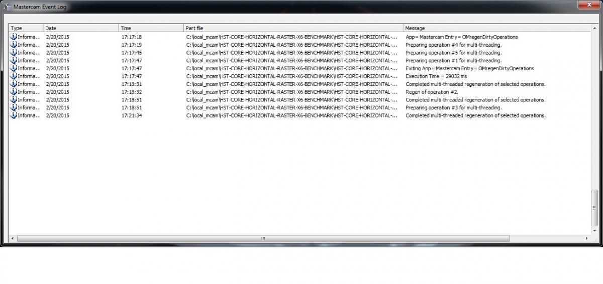
4 Minutes 16 seconds .. not too bad for a 3 year old computer. . System Specs.. Mastercam X8 Asus Maximus V Extreme MB i7 - 3770k O/C to 4.2Ghz 32GB G.Skill 1600Mhz Ram AMD FirePro W8000 w/4GB Video RAM 256 GB Vertex4 SSD 3TB Seagate 7200rpm Windows 7 Ultimate 64Bit
-
1500RPM is almost 500SFM for that cutter.. I wouldn't spin it a whole lot faster than that if you ask me.. also.. that feed sounds pretty darned slow I would probably be going at least 10 IPM and probably 15 IPM so 1500 RPM 15 IPM .02 depth air blast.. that's where I would start.. also depends on insert geometry though.. what facemill? what insert?
-
Computer hardware: Help filling in the blanks please
djstedman replied to sir Camalot's topic in Industrial Forum
You have gotten to the crux of the issue, its easy to recommend the absolute best processor out there when you don't have to worry about cost, once cost comes into the mix it becomes more difficult. Future proof is an interesting concept in that it implies that its possible to know the future. I suppose its possible to make an educated guess, but IMO it is impossible to know what a future proof system really looks like without answering a bunch of questions first. What changes will Microsoft incorporate into their next OS? Will the OS be upgraded when new OS's come out? Will there be new technologies that make a substantial difference in processing speed? What changes will Mastercam make to the software which influence how the hardware handles it? Will Mastercam capitalize on any new technology that comes along that will give a substantive boost to performance? Assuming you can answer all of those, then you need to consider, in three years time.. what is a 'high end' system going to have for spec's and will your system still be robust enough that it will be competitive. I am not saying its impossible to make a system now that will still be good in 3 years, given the slowdown in growth of high end systems over the last few years I think its more possible now than it would have been a 5 or 6 years ago, however there is still no guarantees. If it was my money I was spending, I wouldn't buy one of the high end Xeon's that give a minimal performance gain over an i7 when the Xeon costs almost double for the same level of performance, I would look at it that buying the system that cost half as much would allow me to upgrade in 3 years if necessary whereas buying the system that cost twice as much would lock me into that rig for longer for the same ROI. I haven't run a Xeon so I can't say if a Xeon would be more stable than an i7 due to memory as you suggested, however another programmer here has a Xeon system, and he still crashes occasionally, the company bought his at the same time as mine, it came from Solid Boxx and was about 7k , mine was built from parts and was about 3.5K to build. The two systems were almost even on performance at time of purchase with my i7 outperforming his by a slim margin when we got them, the level of performance has stayed pretty even since then.. with neither system really pulling ahead. When we get new computers we are most likely not going to even bother upgrading these two systems, more than likely we will start fresh with all new components. New computers like new parts, you don't usually buy a new high end CPU and put it in a used motherboard with a slower Front Side Bus than it could handle, or connect drives or video cards that are out of date. Can you? Sure. However you will be degrading the performance of your new components, IMO upgrading a system is generally something people that simply cannot afford to get the parts they really need do to get by until they can get what they really want. In most business situations its easier, faster and more productive to simply replace the entire system. So both the i7 and the Xeon will have had the same life cycle, both have performed equivalently, so the cost would be the main deciding factor to determining the overall value and ROI. So for my system at $3500 it cost about $24.30 a week to run the system for 36 months, for his system which provided pretty much the exact same level of performance it cost about $48.60 a week for 36 Months .. IMO its crazy to pay double for the same thing - its important to note btw that it wasn't simply components that doubled the cost of his system, it was purchasing it from a high end system developer that had to do all this research and decide on components plus build the system and provide support. Either way.. perhaps the most important thing in this entire post is those two numbers representing cost per week, one is $24 and one is $48 .. that's basically on a 6 day week $4 dollars or $8 dollars a day. That is not even close to one hours pay for the lowest paid CNC programmer. The cost for the computer is essentially nothing compared to having a computer that forces your programmer to sit for even 15 minutes a day being unproductive. I guess to some it up, buy the best CPU you can afford, the choice between Xeon and i7 probably makes very little difference assuming the specs are relatively close, and by purchasing a system that limits unproductive time you will easily cover the cost of a high end system.