Chris In-House Solutions
-
Posts
433 -
Joined
-
Last visited
-
Days Won
3
Content Type
Profiles
Forums
Downloads
Store
eMastercam Wiki
Blogs
Gallery
Events
Everything posted by Chris In-House Solutions
-
Mastercam is integrated into SolidWorks. I dont believe it will read your tapped hole information from Inventor but I havent ever tried it so dont hold me to that. However if you created the tapped hole in SolidWorks and were using FBD in Mastercam it would recognize the hole as a taped hole from the Hole Whizard in SolidWorks and then pick the appropriate spot drill, tap drill and tap.
-
The Mill Level 1 book sold on this website covers all the High Speed Toolpaths. It maybe a good reference to start with.
-
If you have a 64 bit computer you will notice great improvements in toolpath calculation times. I had a file which a customer said he couldnt nest on his computer using X5 MU1. I did managed to nest his file using X5 MU1 but it took about 15 minutes. I then saved his fies in X6 and repeated the same process. It took just over 3 minutes to nest the file in X6. I was completely blown away. The preformance improvements alone will make the wait worth while.
-
Mastercam Art Design Library
Chris In-House Solutions replied to whiterivr's topic in Woodworking Forum
Users on Windows 7 cannot preview those art files. It works in Win XP though. -
How to install Mpmaster?
Chris In-House Solutions replied to floo's topic in Post Processor Development Forum
Here is the video. As for editing your code.. this video only shows you how to install the post. To edit the code you would either talk with your reseller or ask around here. Post what your getting and what it is you want. I'm sure someone can help you. -
I am running Nvidia Quadro 2000 video card and do not have those issues. I used the drivers recommended by SolidWorks. So I have version 8.17.12.7090 with a date of 31/05/2011.
-
There is a new (better) way to chain these entities which will allow you to cut the smaller area and leave the larger area alone.
-
Solid Layout Section View
Chris In-House Solutions replied to Brian B 74's topic in Industrial Forum
In order to do section view's you need to create the line and then the arrows. Its not an automated process yet. -
Gary - Glad to hear you have decided to keep your maintenance up. Jeff I'm not sure what it is that you mean by..
-
How to install Mpmaster?
Chris In-House Solutions replied to floo's topic in Post Processor Development Forum
Here is a link to a video demonstrating how to install a mpmaster post. My link Same steps except take the mplmaster.pst and put it in the lathe post folder. -
Try downloading and updating your graphics card driver. It could also be overlapping or duplicate entities.
-
Not sure if we can really comment on this yet but you have the correct idea for what it will do. Playing with it for the past few months I can say it will greatly help you and is definitely worth waiting for X6. You will be happy with it.
-
NCI name Same as Geometry File Name
Chris In-House Solutions replied to Candyman's topic in Industrial Forum
Hey Paul, As long as you save your geometry before staring to create the toolpath's it should take the geometry name and apply it to the NC and NCI name. -
Take a look at the into to multiaxis training tutorial book in the store here.
-
New desktop speed
Chris In-House Solutions replied to Pilot Plant Supervisor's topic in Industrial Forum
When X6 comes out it will support 64 bit. You will notice a huge increase in toolpath calculation time. -
Issues and features
Chris In-House Solutions replied to Teh Bear without Brains kinda idiot's topic in Industrial Forum
I know this only address one of these issues listed here but for the issue listed by guyinthedesert if you use mpmaster there is a misc value that you can switch on so it locks on first WCS. Meaning it will only output G54 throughout your entire NC file. If you don't use mpmaster then put a request into your reseller and I'm sure they can make this happen for you depending upon your machine and post of course. It can be very easy to point out flaws or negative attributes of anything. If you want to be heard then I would suggest writing an email to your reseller and asking them to pass it onto CNC software with your idea's or suggestions. I'm sure with future releases of the software these issues will get addressed and the software will continue to improve. The added features and improved toolpath calculation time in X6 will make it worth while to use.
-
Selecting partial edge curves on a solid can be tricky. It prompt you for the first edge curve then a reference face then the last curve. Depending upon what edge you pick first determines the outcome of this. Why not create curves on all edges and then use the wireframe chaining options. If your determined to get the solid chaining to work for you then try selecting your part differently. Maybe try selecting a top edge of the solid instead of the bottom edge. If its possible can you take a screenshot of the solid and describe how you are tying to select the solid. I'm sure someone on here can point you in the right direction.
-
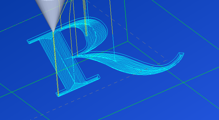
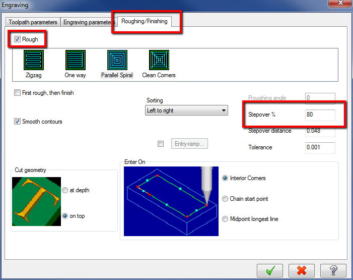
The issue seemed to be that the Roughing method of Zigzag didn't work for this file. If you change the roughing method to Parallel Spiral or Clean Corners then it roughs the part as shown in the graphic below.

-
Below are the steps used to add this using the ActiveReports Designer To output the Manufacture's tool code you need to Select the plus next to Bound, Scroll down to NCFILE choose that plus, pick the plus next to TOOLS, and then the plus next to TOOL. Scroll down and find CODE. Then drag it over to your report and it should work. I have added this feature to an existing report before and got it to work.
-
Hey, What tutorial are you working on? The reason why we used the two toolpath's on the same shape is to show the difference between the two toolpath's. They both accomplish the same thing which is to remove material leaving a standing core. So which one you use is up to you or person preference.
-
Do you want to know the difference between the High Speed toolpath's and the Dynamic toolpath's?
-
If you are on current maintenance or your maintenance expired after April 27, 2011 I would recommend you try downloading MU1, regenerating the program and seeing if that makes a difference. If that doesn't work then a sample file or sizes would be great.
-
Can you put the file up on the FTP and let someone here take a look at it?
-
What version of the software are you trying to use? In X5 look for the Roughing/Finishing Tab, enable Rough and if you wish change your stepover %. By enabling roughing this will remove the material in the letters and finishing will have the tool lift up in the corners.
-
Offset the wall geometry by the radius of the tool and use that geometry as your "Wall" If you want to leave stock on the wall offset the "wall" geometry + the amount of material you want to leave on the walls.