Sticky
-
Posts
940 -
Joined
-
Last visited
Content Type
Profiles
Forums
Downloads
Store
eMastercam Wiki
Blogs
Gallery
Events
Everything posted by Sticky
-
I also had a new to me problem two days ago on a tombstone. I found out that if you have a tool path with only one entity on a plane it ignores the linking parameters "clearance" value, but only on retract, it still uses it on the way in for G43 Needless to say it almost caused a spindle through tombstone situation, luckily I've been on edge with my MC post lately. There had already been a few tools that went to these planes without issues, but because they had more then one entity on that plane they used the clearance value on the way in and OUT.
-
Strange one Joe. I'm quite sure I have done that and I haven't seen that problem. In your transform rotate, is your source geometry or NCI? Do you have two different tool planes for this tool then? And do they have their own work offsets tied to them?
-
G10 output for WCS's based off COR Extended workoffsets A method of being able to transform rotate a transform translate op with extended offsets Productivity plus integration Those are just some of the things that someone who would want to take this course is going to need help having integrated into their post. Sounds like you won't have any problem doing that, but I thought it was worth mentioning because other people will have some or all of those needs.
-
Its a 5" gage length, there will be some deflection. But the cut parameters you are talking about have me thinking its more a squareness issue then anything. Do you have a large 5 sided square you can use to check the squareness of the machine? Retention is one potential and common cause, a worn taper is another. In this case, the long gage length and small diameter are going to be the largest causes of deflection, they just give/bend when force is applied to them. You might be surprised how much a 3/8 carbide end mill will bend before it snaps. I was thinking the same thing, this has long term stress written all over it.
-
Oh and about your "calibration pallet", I wouldn't recommend it. Because then you have to throw pallet repeatability into the mix, and while its usually .0002" or less, its still going to add a lot of tail chasing, and likely for nothing.
-
When trouble shooting, start from base, and work your way out. So, how square is your machine? Do you have values for YZ over 300-500MM? How about XZ? You only need to be 5 microns out or less for either of those to see the error you have. Backlash? The most likely cause of all of this, is the fact that you have a 40 taper holder with a 5" gage length. Depending on the part material and your S&F (cutting pressure) you could easily cut .002" deeper then programmed from deflection alone. Deflection and thermal growth are the reason I haven't bought a presetter. Whenever you change your cutting parameters, or the tool losses sharpness your cutting pressure changes and this WILL affect your cut result, both for wall taper and floor/Z depths. I do as Joe does, 9811 is your friend! The only thing I add to his method is I use (best I can anyways) the same cut parameters (S&F, ADOC, RDOC) that the tool will actually use in the program. This is the only way IMO to get it t1ts. With a 40 taper, and 5" gage, even on a little 3/8 tool, I would PLAN on it cutting at least .001-.002" deep if you are taking any sort of healthy cut. I can actually get a 1/2" em to cut about .01" deeper then set and programmed without getting too crazy. Everything moves and deflects when you put force on it, how much is your responsibility to measure. To prove this use the same tool and take varying depths of cuts, get more aggressive each cut and probe in between cuts. You will see you cut deeper then programmed, incrementally, on each cut. And your wall will have more taper too. A presetter is not going to solve your problems.
-
By G code, yes, by Mastercam... I wish. I think it would be awesome if you guys did a course for this, as I can't find any other training for it. Would you guys modify each users post processor then? Stock Mpmaster lacks some functionality that would be necessary.
-
Are they really that $pendy? I don't think the Okuma, Mazak, or Matsuura cell and fms options I have seen are anywhere near that expensive, even for 12 or more pallets.
-

Method for calculating workoffsets for 4th axis?
Sticky replied to Sticky's topic in Industrial Forum
Unfortunately no DFO on this machine. -
Matsuura Canada and Japan push Gibbs, Matsuura UK pushes Featurecam. Unfortunately all the local machine tool dealers are really small and we don't really have local apps guys.
-
What did they do to it though? I have a 15k Matsuura spindle with around 30,000hrs on it, runs great.
-
Method for calculating workoffsets for 4th axis?
Sticky replied to Sticky's topic in Industrial Forum
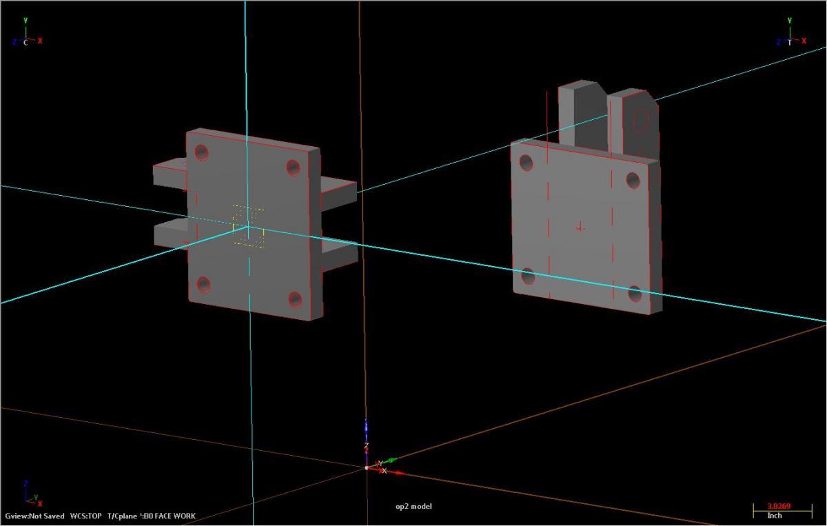
So I have a problem, I am assuming its the way my post is setup, but maybe you guys can clarify? I have two parts sitting on a tombstone, they are the same part #, one part is setup for Op1 on B0, the other part is setup for Op2 on B180. These parts are weldments, and are not flat or square in any direction. My intent, is to probe each face and write the new work offset (because they will be different for each part), and then perform the work on that plane. What I have done is setup new WCS' for each B axis index, which I created by geometry to associate them to the model, so that I could have the parts fully programmed before actually mounting them to a tombstone and finding their positions on the machine. Now I have found their positions on the machine, and offset the two parts from my center of rotation in Mastercam so that my post can create the correct offsets for each plane. Here is my Op1 part mounted on B0: And the Op2 part that is mounted on B180, but this wcs is on B90: And the same Op2 part mounted on B180, but now the B270 wcs: On all of my tool paths I have "Working coordinate system" set to TOP, and the Tool plane and Construction plane set to what custom wcs I made for the plane. The problem is that the G10 values that are being output are only correct for the part at B0. If I create any additional wcs's for doing side work on my B0 part my G10 offsets are fine. The post output G10 X and Z values are out to lunch for the part on B180, for both the B90 and B270 offsets. I am wondering how I am supposed to have parts not in the FRONT space, and set ups wcs' for them, and get this G10 output to work

-
Does anyone here know where I could get some training on using MC to program hmc's with multiple parts, planes, workoffsets and in process probing? I'd consider traveling for in classroom training. But text would be preferable. The In House Indexing manual doesn't go anywhere near this level of detail, and so far non of the In House tech guys I have talked to have done anything beyond that. I am wasting about 10 hours a week in programming, trying to get stuff to work either by myself or with In House support and I am getting frustrated.
-
Yikes, have you priced out some pallets yet? For a 400mm machine they usually go for 4-8k/pc... Don't worry about the RGV speed, if that becomes a problem for you the work isn't suited for a fms anyways... I'd be curious to see how updating the fms goes. I would sure prefer my old style 3 high fms, and add a new Matsuura Hplus 405 instead of the new style fms' that take up twice as much space with half as many pallets How did your inspection of that system go anyways? Sounds like you are being swayed in the ways of the fms
-
It works fine for me if that created wcs stays stuck to the geometry, the issue for me is if I create a wcs from geometry, but then need to shift the wcs to better suite where it resides on the model, the associativity is broken. I am just wondering if there is a way around that, or if I always need to create new geometry and a new wcs if I need it moved on the model.
-
When you make a custom WCS is the only way of maintaining associativity to a model via "create by geometry"? The problem I have with this is if you need to make a small shift to that wcs you lose associativity, unless I am missing some sort of trick? Is there a better method of setting up new WCS's for multiple planes?
-
What are you guys doing for second ops? The Lang softjaws or?
-
As far as I know the Matsuura mx-520 has that part of the market cornered. I'd say go to St.Paul and do some test cuts. They are great machines. You will love the spindle!
-
Do you guys have issues with imported ops functions not working in the new file? Things like "force tool change" "rapid retract" etc, for some reason sometimes when I import operations these and other functions simply do not work.
-
Making due with what you have.
Sticky replied to Chipmakr's topic in Machining, Tools, Cutting & Probing
I've seen that one a few times. I really like the attitude and idea, parts wouldn't exactly be showcase samples but its just too creative to really bag on it. -
How did you visit to the shop with the fms for sale go Bob?
-
Wow, that is a great price if the mill isn't completely worn out. Is it a stacker system? Mine stacks 3 levels high, and on BOTH sides of the RGV, Total footprint including machine is 20'x22' Speaking of which, does anyone know why its not more common to stack on both sides of the RGV, or at least the machine side? Stacking on the opposite side just makes the whole system bigger, seems like wasted space.
-
Oh and as for the RGV thing, in the almost 20 years this fms has been going, the RGV has gone down twice, servo packs both times, 1 day overnight for a new pack and back in business. So in my experience I'd say the machine is much more likely to go down then the RGV. I wouldn't put much worry into it. The nice about the fms is, even if you do get a day behind its easy work to play catch up.
-
I have a 27 pallet single spindle FMS. For me, its more productive then two, 2 pallet hmc's. I do not have the man power to setup, and prove out programs on two spindles, or take care of the added maintenance, coolant and chip control for two spindles etc. I do a fair amount of repeat work, but these days the qty's are getting pretty low, but at least I can have pallets permanently setup with jobs. This to me is the biggest time and money saver of all, if I need to run a job I load raw stock and press go. With two pallet hmc's you are likely loading fixtures, adding tools etc. For short run or prototype work I still like having lots of pallets. I have 1 drilled and tapped angle plate, 2 big t slot angle plates, 3 double lock vice tombstones, and a couple spare pallets all ready for one off or low run work. And with the tool Matrix, any tools that get loaded in the machine usually permanently reside there. So rarely do I ever load tools for one off jobs unless I have to buy something new. So just with the above pallets I can have 6 different 5pc qty jobs, and run them all simultaneously, and if they match the material of the production I am running at night then maybe they get thrown into the night shift schedule too. If I had the man power, and no repeat work I'd take the two spindles every time. But for repeat work its hard to ignore the extra pallets.
-
How much for the 2' one? pics?