Sticky
-
Posts
940 -
Joined
-
Last visited
Content Type
Profiles
Forums
Downloads
Store
eMastercam Wiki
Blogs
Gallery
Events
Everything posted by Sticky
-
If its shaking the machine that much there is an issue with the actual machine level and squareness (tool changer aside I mean).
-
Sounds like the machine TCS was selling.
-
Good to hear you got a new job! What kind of machine and pallet system is it? As for your code problem, have you checked the offending tool paths to see that you have the correct WCS selected? And also double check the Misc Values, you want "lock on first wcs" set to 0. Are you using transforms?
-
So you are thinking of doing everything inside the post?
-
Yes I can, and I can write values there via G10. The post is already setup to output J, so that is covered. The problem is transforming a translate/transform operation.
-
Not a Haas. I already do in process probing, for setting offsets and inspecting parts. I think you are missing what I am doing, read post 51 again.
-
Oh Durrr, you're right. G54.2 and TCP would be nice upgrades, but would likely need at least an Eprom upgrade? Might be spendy (but worth it), but might be a hard sell if they bought 5 axis machines without probes...
-
If you aren't moving them from machine, and they are more or less dedicated to a machining center it is much easier to just change the Z axis grid shift then to grind or shim the tables. Make sure you shift the tool change position by the same amount, or even better, use the opportunity to set the tool change position properly (rarely done correctly by most techs).
-

Tools of coolant video
Sticky replied to Rocketmachinist's topic in Machining, Tools, Cutting & Probing
That is a great video. I've had to train every person that has worked here on coolant maintenance, this just made my job so much easier. Same with the Haas softjaw cutting videos, now I just get employees to watch the videos before I go over it with them on the machine. -
I missed the part about picking the point after the two lines, I will start doing it that way and see if it increases the reliability for me. Thanks guys
-
What is the advantage to doing it that way? I'm not seeing any advantage over having offsets for each part/face. Can you provide an example of the transform tool path doing what I am asking for, both in this thread and the above link?
-
IIRC you get about 100mm extra Y on the Hplus800. Still kicking myself for not grabbing an almost new Hplus800 a couple years back.
-
I'm in the exact same spot, I'm doing setups now too. Better then having no work, but it is a lot of hours and it makes software issues much more frustrating.
-
I hear you on that one. I feel the same way. Waiting is getting a bit painful though.
-
Kitamura is nice heavy duty machining center, no where near comparable to that Haas, it is several classes higher. Joe brings up a good point though. If you have high MRR make sure the machine can actually handle it. Also squareness become a big deal on these machines with all that Y travel. Definitely visit some actual users and see how they like the service and support. Big machines cost big $$$ and downtime can sink you quick, make sure the MTB has you covered (and don't just take their word for it). While you are looking at the Kitamura I''d also look at Matsuura, Makino and OKK. They all have heavy duty HMC's and some experience building them.
-
Cool, thanks for the info Carmen.
-
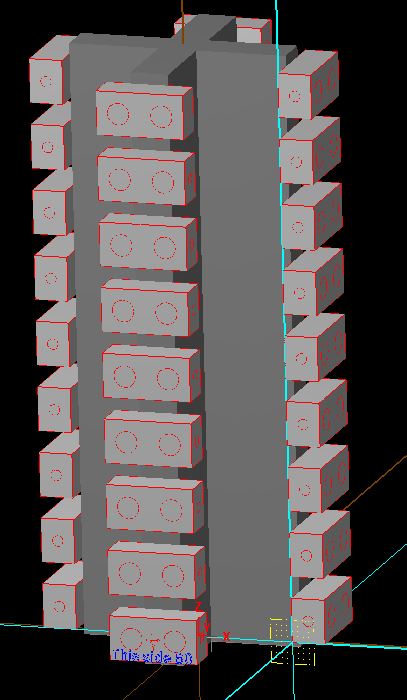
CJep, not really. What I want to do it is program one part, then populate it vertically in the Y axis, and then on 2-6 sides of tombstone while maintaining individual offsets for each part. The above picture is just a quick dummy model to test transform ops. What I want to do is use G54 for parts mounted on the B0 face of the tombstone, and add G55-59 based on how many sides of the tombstone I have. So a two sided tombstone would use only G54 and G55, while a six sided tombstone would use G54-59. And any side work on the parts would use the extended offsets for that side. IE G54 is for parts on B0, so side work on a part mounted on B0 would use a G54 P12 etc My controller uses J1-27 for extended offsets. So that is what I will use for the rest of my example. What I would like to be able to do is program the bottom part that is facing out (B0), working on the face, right and left sides. I want the face of the first part to be G54 J1, then transform the tool paths Y+ to get a total of 9 parts, G54 J1-9. Then I want to work on the right side, starting at the bottom I would use offsets G54 J10, and transform up to G54 J18. Then on the left side start at G54 J19 and transform up to G54 J27. Now that all the parts on B0 are complete and ready to go I would like to just transform to the other 4 sides. So parts on the B90 side of the tombstone would start at G55 J1 for work on the B90 index, and go to G55 J9, right side of those part G55 J10-18, and left side G55 J19-27. Yes you could use G52 or something and work shift, or use the same offset for each face, and write over it each index using G10 or something, but both of those methods introduce more headache and problems then just having dedicated offsets for each face. And no transforms for multiple parts on multiple panes is not so great, go back and read the link I posted earlier. Sure its fine if you only have one part on each index, or if you are just translating parts on one plane, but anything beyond that it takes a lot of post modifications to get it to work.
-
I'm waiting for the Bonkers X8 review. Have you considered looking at other software Rickster? It sucks to have to make a switch, but if are losing enough time in a week it might be the most "affordable" route.
-
The way you are doing it now has been the most reliable method for me. I was building a library of operations to import to a new or existing file, but I have had some reliability issues. Things like "force tool change" won't work, some issues using imported ops that had a custom wcs associated to them previously won't marry the new custom wcs you want to associate to it etc. One time we had an issue with either copying a drill path or importing it, I can't remember which, where I had finished drilling a set of holes with about a 5/16" diameter drill about 10" long, the machine retracted to the clearance plane, shut the spindle off and started to head home for a tool change(how our post is setup), and then cranked the spindle back on to about 10k rpm (only about 5x more then the programmed spindle speed)!! Needless to say the drill bent 90*, good thing no one poked their head in there, that would have been game over.
-
Are there any precautions for mounting heavy duty magnets to CNC machines? Seems like they could potentially give you some issues with drives and stuff.
-
I've been using wcs by geometry only for the last few weeks now. It works ok, it still breaks sometimes, I haven't nailed down the cause yet but it certainly has been a better method.
-
Works fine if you are working with parts with loose tolerances, that can be located at the same position every load. For everything else its not so good. It works fine if you want one offset for the entire program, or one offset per face. It does not work well for multiple offsets, or multiple parts. http://www.emastercam.com/board/index.php?showtopic=76406
-
You're such a hack Joe, leave it on 100% all the time
-
CAM for on machine programming
Sticky replied to gcode's topic in Machining, Tools, Cutting & Probing
Yeah I guess its not too big of a deal to do the mnp. -
No I haven't looked at it. How do you like it for 4th work? Is a code backplotter only or can you have your part model in there and everything?