mikenaturalice
-
Posts
138 -
Joined
-
Last visited
Content Type
Profiles
Forums
Downloads
Store
eMastercam Wiki
Blogs
Gallery
Events
Everything posted by mikenaturalice
-
Anyone Ever Use Pencil Mill Before Finishing?
mikenaturalice replied to Reko's topic in Industrial Forum
I used to do this all the time. it will take more stock, depending, but I would do like specv and leave a bit-o-stock and then come back and do a 'finish' pass. Funny now that I think of that because the work I do now I rarely ever have to finish like that just because the work is different... Weird how at one time that was my 'go to' surfacing op/procedure and now that I think of it have not done that in years. Not that I found a different way, just the parts I do are different. -
Alternatives to Pibull clamps
mikenaturalice replied to dstryr's topic in Machining, Tools, Cutting & Probing
Have you contacted MiteeBite or a distributor? I would imagine you could work out a discount if you do need to order 400 at once. I am with you on cost though, last fixture I started designing got very expensive when I figured for hardware and machining time... -
Do you move your part or Make a new WCS?
mikenaturalice replied to Pitka_Guru's topic in Industrial Forum
My post gives me an error if I am not using the default TOP as my wcs. I don't know if I could work around that or not... I normally move my part to the top wcs in the orientation I am going to start machining it and program everything (at least the 5 sides I can get to) from there. When I machine the bottom of the part I am usually using a fixture to hold the part so I make a new program using the fixture and having the part mounted in the fixture with the bottom ( the section of the part that is held in the vise, does not have to be the 'bottom' ) of the part as my new top wcs. -
I don't know if that is possible. I seem to remember it in X6 maybe? I checked my install of X7 and it is the same, F9 shows the current wcs plus the origin. Anyone know if there is a setting somewhere to change this?
-
I completed a 4 year apprenticeship that was certified through the department of labor. I think I only ever interviewed for one or two jobs where they were interested in seeing my 'papers'. I also did the Mastercam mill 1 course at the resellers place where they did training. It was a one week course and I got a certificate, but again, not too many employers care from my experience.
-
Fairly new to A2 and progressive die process
mikenaturalice replied to dforsythe's topic in Industrial Forum
You are not going to ream anything at 60rc IMO. I would drill the dowel (I presume) holes with an 1/8" drill and wireburn after HT and grinding is done. You can drill and tap the holes before HT, they will not move enough to cause an issue, if they move it will be very minimal. Maybe oversize tap them if you want, but you don't really need to for A2. -
I just noticed that mine too runs the post processor first, at least I get the box in the upper left corner saying "initiate opening post processor files". It does not actually post the gcode, but it has to complete the post processing before the machine sim starts up. Do you think mine is reading the gcode too? Same people/company. Is it for a Haas UMC-750 by chance? Mine is a little buggy. I heard via my reseller that the metric version ran fine but the inch version had a few issues. I have not tried the translation in x or y on a real part, but I do use the Z translate. I will try putting numbers in x and y and see how that affects the simulation. I can get all of these numbers easy enough by doing the math from the machine absolute coordinates. I know the Z is pretty important, did not think to check x and y (on the machine I mean), but they are close because I have a 3/8 pin on the bottom of my fixture and the table has a 50mm bore at center so I can't be too far off center. I purposely took out my centering plug before I ran the last part to see how the dynamic work offset worked, and to make sure it did indeed work.
-
Hey guys, just found out about a multiaxis problem in X8. Maybe this is old, if so my apologies, feel free to ignore this. If you are in a multiaxis path and you use the disk save icon in the upper left corner, sometimes (not sure what all paths are affected) it will make it so only the parallel cuts is available afterwards. Just learned this yesterday from my reseller after I could not get anything but classic and mill/drill to work in the multiaxis paths. It would show the proper name in the upper left corner, like swarf milling or whatever, but the surface/solid button and parallel cuts would be highlighted in the menu.
-
19 flutes? Are you sure you are not looking under burrs? LoL. You say a 5% stepover so you are roughing with it I assume? Is that in the multimaster line, or just their solid carbide tools?
-
I could not find that Colin. I did see there is a whole lot that I don't understand with this post so I am just going to wait for my reseller to get it done for me.
-
Thanks for the help CJep. I have the center roughed out to straight walls, that is the easy part. I looked at your file and it definitely started me in the right direction. I wish I could upload the full part here. My reseller also offered a toolpath, but lets just say it was a little bit lacking (not that I know what I am doing, but what I got was just like the tip of the iceberg to get me started). He (the reseller) also mentioned that it was a very hard part and he had to get help with it, so I guess I don't feel so bad being a complete novice and struggling so badly with it. For what it is worth I used to think I was pretty clever with MCX and using alot of the tools and toolpaths to get some creative sh*t done. I feel very very humbled now!
-
Mastercam X9 Public Beta now open
mikenaturalice replied to Jim Evans from CNC Software's topic in Industrial Forum
Thanks gcode! Hopefully the server is not too busy right now... -
39 downloads and no tips or feedback for me? Am I trying the completely wrong type of path for this? I promise not to hold anyone liable if I scrap the part!! hehe
-
Mastercam X9 Public Beta now open
mikenaturalice replied to Jim Evans from CNC Software's topic in Industrial Forum
I was told X9 was being released on May 1st. I see on the Mastercam website it still says X9 public beta. Anyone have any information on this? -
I am hoping someone here maybe knows where to look for this. The UMC has an option (which is turned on in my machine, I checked already) to not unwind the C axis, but to go to the closest position to take it home and ignore all the extra revolutions. The catch is that the code has to be posted as "G91 G28 C0.", not the G53 C0. that the post now outputs. I have asked my reseller and he is looking into it, but I thought I would ask here in case someone has already done this. Here is a bit of sample code and what I want to do - (this was the last few lines before the M01 and tool change) X.0068 Z-.5852 C-5310.214 (this takes a little while to unwind to C0, trying to avoid this) Z-.5229 Z5.0251 F600. X.0075 Y2.017 Z5.3715 X.0083 Y2.217 Z5.7179 Z6. G187 G49 M05 G00 G53 Z0. M09 (safe Z move to clear tool away from part and table) G53 Y0. (safe Y move to get tool back away from rotary table) M11 M13 G53 B0. (original code has C0. On this line) G91 G28 C0. (NEW PROPOSED LINE OF CODE, AFTER THE G53 B0. IS POSTED) M01 Any help would be appreciated.
-
Speaking of ghosts... I backplotted after the change then switched them all back to top and backplotted again and all was good. I copied the toolpath to do the drilling and BAM, back to the same weird backplot. I posted the code and it is fine... oh well, hope to see X9 soon!
-
I changed them all to front and it backplotted correctly!! I ran the machine sim but got an error saying it only supported the top plane (or something like that). I then changed them all back to top and it backplotted correctly ... Thanks for the help!
-
Hey guys, hoping for maybe a bit of input. I tried using the cavity collision control curve path on my part and it sort of worked. It actually seemed to do ok except where the 'humps' in the floor of the part are. There it tilts the tool so the tip of the ball (along the tool axis line) is perpendicular to the surface, which in turn runs the tool at about 90 degrees to the part and runs the tool and holder into the part. Is there a way to make the tool cut on the side of the ball in this area? I used a chain around the top of the boss and the top of the 'od' of the reverse taper section.
-
It was off, I tried turning it on and had the same effect. Thanks for the help though. It seems to be a problem with my system at this point. My reseller file that I sent him backplots fine, but I got the same weird behavior when I opened his file. I sent it to Mastercam on his (my reseller) request and they said I needed to set a safety zone. Two problems I saw with this, well 3 actually, 1) his file backplotted fine without a safety zone 2) the safety zone defaulted with the tool running underneath the part (maybe a setting I had screwed up) 3) When I did get a safety zone set up properly the machine sim showed a very jerky motion as the tool was moving up and down in Z as the trunnion was rotating to the other side of the part. Not sure what the code looked like for that as I did not try posting since it looked so bad visually. p.s. wcs, tool, and construction are all set to top
-
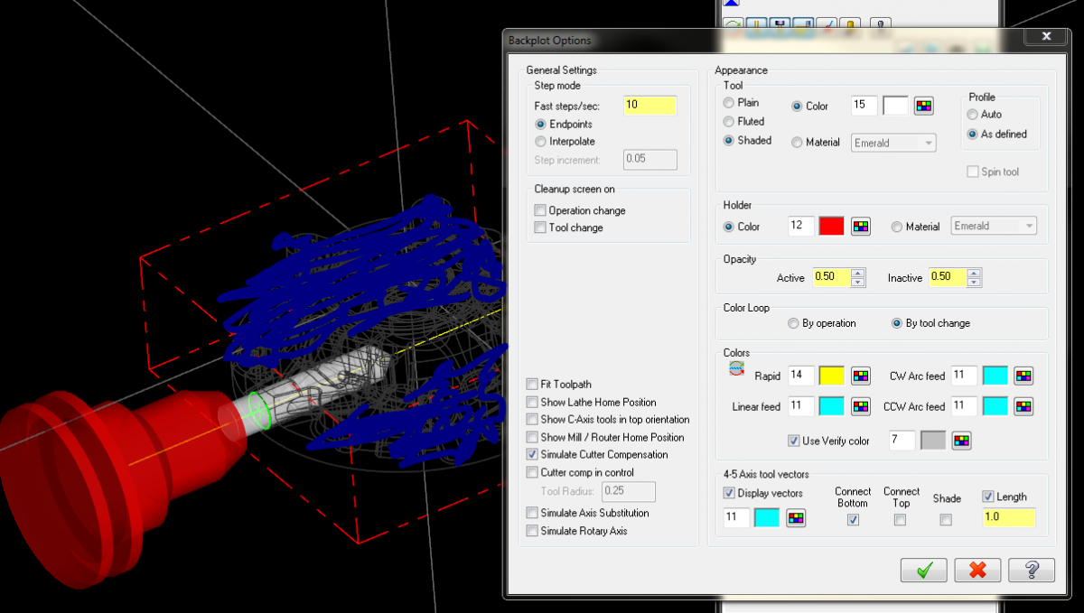
Has anyone seen the backplot for 5 axis drilling run completely through the part and then flip the tool 180degrees (inside the part) and do the same on the opposite side of part?? I have been working with my reseller and he is stumped, calling Mastercam now to hopefully get an answer. Oddly, His part is fine, and he even sent me the part he did and when I backplot I get the same thing (tool running completely thru). Hopefully you can see my backplot options and let me know if something looks off. My reseller compared his settings to mine and they are the same. Oh, forgot to mention, the machine simulation looks fine, it spots, retracts, indexes and spots again no problem. The code also looks fine, but the verify shows the tool and holder going through the part just like the backplot. I do have my verify set to 5 axis as well.
-
You should see the real part! My plan is to hold it in a 5th axis vise as a 5x5 square (the part is significantly more involved than the little bit I posted) and rough around the perimeter and rough around the center boss with just a hs surface path. I know I can create planes to do alot of the machining around the perimeter for flats and features, its just that center that I have no real clue how to approach. After I get it out of the vise I am planning on milling soft jaws to hold it and do the backside. Definitely two ops no matter what.
-
I am new to 5 axis programming. I have done just a smidge with flowline and rotary (about 1% honestly). I have enclosed this dumbed down part example. Sorry I can't upload the real file, but this is similar. I have a center boss with a drafted wall around it that starts with a small diameter at the top and fans out at the bottom, like a chemical beaker/container. I did not put any toolpaths on this sample. On the 'real file' I have tried doing a hs surfacing and then converting to 5 axis with no luck. I tried the multisurface but I keep getting a flowline or partial flow edge error. I really don't even know where to start with this. I also tried the multiaxis roughing but I am confused about how to select my maching surfaces/faces. When I click on floor surfaces it goes to the graphics window and asks for check surfaces, same thing with wall & check surfaces, it goes to the graphics windows and asks for check surfaces? I also don't get the ceiling surfaces. How can i have a ceiling surface, wouldn't the tool automatically violate that by cutting into the material? It seems to me that this would be relatively simple, as in the machine would rotate (in the B axis for the UMC) to make the walls normal to Z and then just do a hs type path while rotating around the C axis. Maybe I am way off base on that though. I am also wondering if the cutouts in the part are screwing me up? There are actually 6 of them, 4 coming in thru an angle into the 'hump' like features on the floor, and 4 more equally spaced, but coming thru intersecting the wall and floor both at about a 30 degree angle. For the record I am trying to get my company to buy the 5 axis tutorial books for X9 (which I hope is released very soon so I don't learn the wrong stuff LoL). I don't expect to come here and have someone program my stuff, I am just looking for some help to get started until I can get some learning material. thanks for all the help!! 5 axis help.mcx-8
-
Mastercam X9 Public Beta now open
mikenaturalice replied to Jim Evans from CNC Software's topic in Industrial Forum
I just got the notice today saying X9 pre-release version will expire in 2 days. Will there be a new beta to download? Anyone know when the 'official' release of X9 will be? -
Cutting Tool Tolerance
mikenaturalice replied to Brian B 74's topic in Machining, Tools, Cutting & Probing
That sounds right to me. I use some inexpensive endmills and find some of them are +0 -.002", (cutting diameter) and then the really cheap ones are +0 -.005"! That is on 1/4, 3/8, and 1/2 too! Now I have found even on these two different tolerances that most of my tooling comes in about -.001 -.002". Maybe the .005" is 'just in case' -
I brought this up before and was told it was because Mastercam does not calculate accel and decel. On a part I did with alot of dynamic milling I had to add 40% to Mastercam's cycle time to get close to actual.