


pullo
-
Posts
464 -
Joined
-
Last visited
-
Days Won
2
Content Type
Profiles
Forums
Downloads
Store
eMastercam Wiki
Blogs
Gallery
Events
Everything posted by pullo
-
Yes you can change the graphics in the drill parameter pages. I described this here a couple of yrs ago... Gracjan
-
that's exactly it in a nutshell , a tool to find and replace strings in binary files. Gracjan
-
No , I mean that instead of having a Toolpath op named "Steep Parallel Rough" , you could shorten it yourself to "STEEP" . Gracjan
-
I was asked this question by two guys in a very short period of time , so I thought I'd answer this one , here. The short version is that you have to go into the relevant , binary dll files and change them from there. The long version is that this is what the people translating Mastercam into other languages have to do. For this they use a program called SDL Passolo. There are other programs to achieve this , but as CNC uses this , it has become the de facto standard in this community. Gracjan
-
Need a post for version 7.1 to Haas for DM1
pullo replied to norseman9's topic in Post Processor Development Forum
I had a few files from v.9. I discovered that I can open them with X5 , save and work with 2021. I'm pretty sure there must be a way to get to 2021 with only one stop in between .( it could be X5). Gracjan -
Just tried the link in the first message and it worked just fine for me. Gracjan
-
use the old school one? Gracjan
-
there is no functionality in Mastercam to support point clouds. You need the full Ernie software to create surfaces. unless of course your point cloud was done using mechanical digitizing , then you have an organized point cloud and you can manually work on it. Gracjan
-
Yes. Gracjan
-
I got a computational error in dynamic today (my first ever in dynamic). I resolved it by converting the solid to surfs . Gracjan
-
Read up a little bit on this variable. The max allowable value is 64000. I tried to run it with a value of 40 000, but it had detrimental effect on MC . The opening of the chaining menu slows down among other negative stuff. Also Mcam would suddenly crash even if nothing was being done on the screen. So 20000 it is for now.... Gracjan
-
5AX Sawrf with Cutter Comp - Heidenhain 640
pullo replied to Greg Williams's topic in Industrial Forum
You would need vector output , not XYZ AB output to be able to move the tool in the right direction away or into the material.... Gracjan My bad ... you do have vector output on some of the lines. I'll have to try this on my machine..... Gracjan -
There is no automatic method to convert a toolpath into a chain , so I added a C-angle routine to pline$ , as Polar Conversion is nothing more then outputting the C angle of a point to the three other axes on an NC-line (at least in Heidenhain). Gracjan
-
the only toolpath that outputs a correct polar conversion in my post at the moment is a profile. I could not find an error in the post , but by manually converting 3x-toolpaths to a 3-d profile and the post correctly working in this "mode" I was able to move forward with the project.... All the 5-ax posts I tried did not have polar conversion working so I don't even know if it's an Mcam bug or my post. The part is 500 mm in diameter , but my DMU60 moves a little over 160 mm in linear X over the centre, so polar conversion keeps my tool stationary in the - X work zone while the C chugs away . Gracjan
-
I can do this manually by saving the toolpath as geometry and then chaining it manually , but the process can be tedious ... Gracjan
-
one file is worth more than 7600 words Gracjan
-
5ax DWO on Heidenhain TNC530i
pullo replied to huskermcdoogle's topic in Machining, Tools, Cutting & Probing
A machine with a 530 HH is capable of taking a program created on Mcam, where you don't need to know anything about the tool lengths or the distance from the part from the Centers of rotation . You can position your part anywhere on your table and you will get an identical part every time with no reposting. For that you need a post using the PLANE or CYCLE 17 command for 3+2 work and M128 for 5-axis work. Mastercam has finally created a Generic 5-axis post which you can try out before making any monetary decisions. Programming a 5-axis machine using COR can be a thing of the past... Gracjan -
drew a rectangle and alt-e'd two lines. Chaining looks OK. I have used 2021 for the past half a year with alt-e being the main geometry filter and have not seen any erroneous activity... Pullo ....might be something else...
-
Leon82 ,do you mean there is a light version of Cimco CC Probe?
-
It's not even listed as a product and I heard about it from a "guy" so I'd say no it's part of the full Cimco. I think you mean a package called Cimco Software. https://www.mastercam.dk/probing/product/
-
JoshC did you make it work in 5 -ax? I have yet to play with m1 -m9 to output the correct x and y values inside the cycles. Gracjan Leon82 ,what do you mean by "full" Cimco ? Gracjan
-
Just tried free form surface probing and the results are very interesting..... More about them next week. Gracjan
-
There is an example post in the documentation , which does not post , but it let's you use the c-hook , as the c-hook checks if you have the xml configuration added to your post. If you e-mail Dennis at Cimco , he will send you an example working post . Gracjan
-
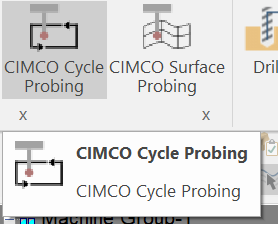
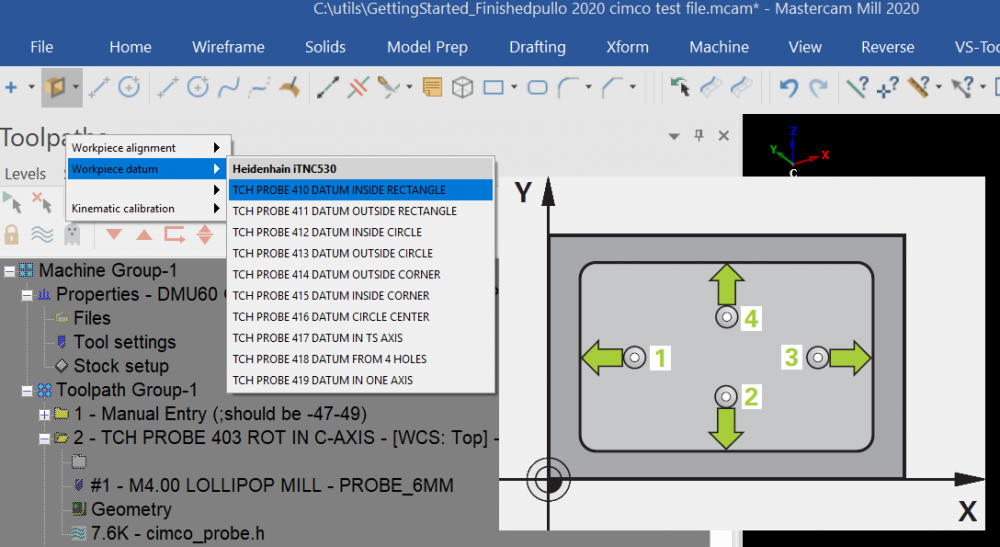
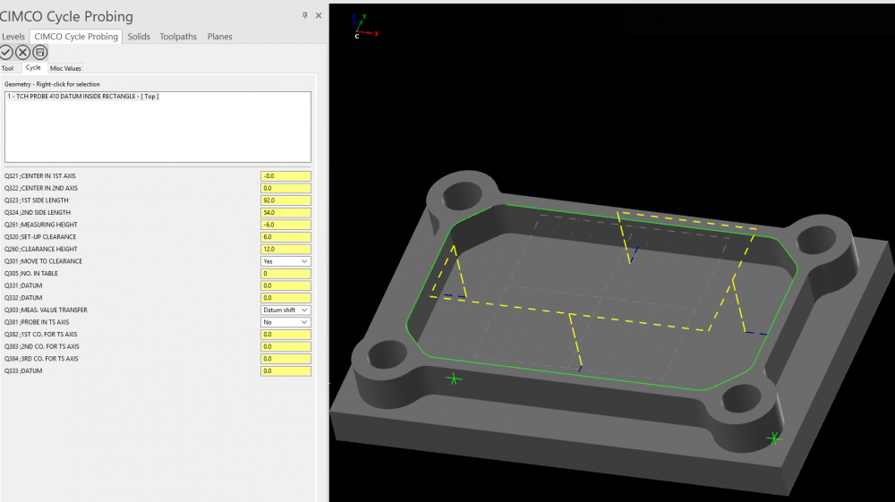
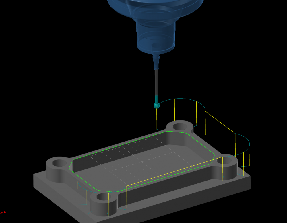
I finally got the Cimco probing C-hook integrated into my posts and only the 5-axis output is still not done , but I have basically gotten the gist of it , so here is a small independent presentation. In order to get the C-hook to work one should integrate the Cimco supplied post code into one own's post processor. After a few days of tinkering with it , my third , 5-axis post was up and working in about 10 minutes from scratch. So it's easy once you know what you're doing ( ok , this statement is basically universal ). I was interested in Heidenhain , so this will be HH heavy. But there's code supplied for Siemens, Haas/Reni , Mazak, Fanuc etc. I heard about this c-hook thru' the grapevine when we had a seminar about Verisurf earlier this year. The c-hook starts off with a choice of Cimco Cycle Probing or Cimco Surface Probing. If you choose probing then you can choose from the following menu : Workpiece alignment, Workpiece datum, Workpiece measurement ( not visible in the pic below, some graphic issue) and Kinematic calibration - an HH add on. I chose the Datum Inside Rectangle , which looks like this on the parameter page : And here is the code for a few cycles : 0 BEGIN PGM CIMCO_PROBE MM 1 M28 M129 ; Pullov:5.15 11:32 22-07-20 2 PLANE RESET STAY ; TYOTASO OFF 3 *-;T=1 DIA=4. R1=3. TXT= ;> tool 0 .1 10. 5. 0. 10. 30. 50. 40. 10. 40. 30. 0. 10. 1 1 0 -80. 4 L Z-1. FMAX M91 ;RAPA4 5 *-Toolpl ORIGO X0. Y0. Z0. 6 * -TOOL NAME: Probe_6mm 7 L B0 C0 FMAX M70;LASTUKULJETIN ON 8 CYCL DEF 9.0 DWELL TIME 9 CYCL DEF 9.1 TIME 2.0 10 ;TOX X0. Y0. Z0. Error < 0.005mm 11 *-_GF_ T=1 HALK=4. NURKAN R=3. 12 *TP: Top WCS= Top 13 TOOL CALL 1 Z S00 14 M22; B-LOCK_A 15 *;CIMCO CC 2+3 ANGL OUT START SOF 16 CYCL DEF 19.0 WORK PLANE 17 CYCL DEF 19.1 A0. C0. 18 *-ANGLES: A0. C0. DMGbhflag=1 19 ;TOX X0. Y0. Z0. Error < 0.005mm 20 *;CIMCO CC 2+3 ANGL OUT END SOF ;NO PRM INFO AVAILABLE 21 TOOL DEF1 22 L X-47. Y-49.001 R0 FMAX ;MOVE_sof 23 L Z12. R0 FMAX ;MOVE_sof 24 TCH PROBE 403 ROT IN C-AXIS~ Q263= -47. ;1ST POINT 1ST AXIS~ Q264= -40. ;1ST POINT 2ND AXIS~ Q265= +47. ;2ND POINT 1ST AXIS~ Q266= -40. ;2ND POINT 2ND AXIS~ Q272= 2 ;MEASURING AXIS~ Q267= 1 ;TRAVERSE DIRECTION~ Q261= -6. ;MEASURING HEIGHT~ Q320= +6. ;SET-UP CLEARANCE~ Q260= +12. ;CLEARANCE HEIGHT~ Q301= 1 ;MOVE TO CLEARANCE~ Q312= 6 ;COMPENSATION AXIS~ Q337= 1 ;SET TO ZERO~ Q305= 1 ;NO IN TABLE~ Q303= 1 ;MEAS. VALUE TRANSFER~ Q380= +0. ;REFERENCE ANGLE 25 ;TOX X0. Y0. Z0. Error < 0.005mm 26 ;>PTLCHG0 27 *TP: Top WCS= Top 28 L X-69.001 Y0. R0 FMAX ;MOVE_ptlchg0 29 L Z12. R0 FMAX ;MOVE_ptlchg0 30 TCH PROBE 411 DATUM OUTSIDE RECTANGLE~ Q321= +0. ;CENTER IN 1ST AXIS~ Q322= +0. ;CENTER IN 2ND AXIS~ Q323= +120. ;1ST SIDE LENGTH~ Q324= +80. ;2ND SIDE LENGTH~ Q261= -6. ;MEASURING HEIGHT~ Q320= +6. ;SET-UP CLEARANCE~ Q260= +12. ;CLEARANCE HEIGHT~ Q301= 1 ;MOVE TO CLEARANCE~ Q305= 1 ;NO. IN TABLE~ Q331= +0. ;DATUM~ Q332= +0. ;DATUM~ Q303= 1 ;MEAS. VALUE TRANSFER~ Q381= 1 ;PROBE IN TS AXIS~ Q382= +0. ;1ST CO. FOR TS AXIS~ Q383= +0. ;2ND CO. FOR TS AXIS~ Q384= +0. ;3RD CO. FOR TS AXIS~ Q333= +0. ;DATUM 31 ;TOX X0. Y0. Z0. Error < 0.005mm 32 ;>PTLCHG0 33 L X-58.001 Y0. R0 FMAX ;MOVE_ptlchg0 34 L Z12. R0 FMAX ;MOVE_ptlchg0 35 TCH PROBE 424 MEAS. RECTAN. OUTSIDE~ Q273= -0. ;CENTER IN 1ST AXIS~ Q274= -0. ;CENTER IN 2ND AXIS~ Q282= +98. ;1ST SIDE LENGTH~ Q283= +60. ;2ND SIDE LENGTH~ Q261= -6. ;MEASURING HEIGHT~ Q320= +6. ;SET-UP CLEARANCE~ Q260= +12. ;CLEARANCE HEIGHT~ Q301= 1 ;MOVE TO CLEARANCE~ Q284= +0. ;MAX. LIMIT 1ST SIDE~ Q285= +0. ;MIN. LIMIT 1ST SIDE~ Q286= +0. ;MAX. LIMIT 2ND SIDE~ Q287= +0. ;MIN. LIMIT 2ND SIDE~ Q279= +0. ;TOLERANCE 1ST CENTER~ Q280= +0. ;TOLERANCE 2ND CENTER~ Q281= 1 ;MEASURING LOG~ Q309= 0 ;PGM-STOP IF ERROR~ Q330= +0. ;TOOL NUMBER 36 ;TOX X0. Y0. Z0. Error < 0.005mm 37 ;>PTLCHG0 38 L X-36.999 Y0. R0 FMAX ;MOVE_ptlchg0 39 L Z12. R0 FMAX ;MOVE_ptlchg0 40 TCH PROBE 423 MEAS. RECTAN. INSIDE~ Q273= -0. ;CENTER IN 1ST AXIS~ Q274= +0. ;CENTER IN 2ND AXIS~ Q282= +92. ;1ST SIDE LENGTH~ Q283= +54. ;2ND SIDE LENGTH~ Q261= -6. ;MEASURING HEIGHT~ Q320= +6. ;SET-UP CLEARANCE~ Q260= +12. ;CLEARANCE HEIGHT~ Q301= 1 ;MOVE TO CLEARANCE~ Q284= +0. ;MAX. LIMIT 1ST SIDE~ Q285= +0. ;MIN. LIMIT 1ST SIDE~ Q286= +0. ;MAX. LIMIT 2ND SIDE~ Q287= +0. ;MIN. LIMIT 2ND SIDE~ Q279= +0. ;TOLERANCE 1ST CENTER~ Q280= +0. ;TOLERANCE 2ND CENTER~ Q281= 1 ;MEASURING LOG~ Q309= 0 ;PGM-STOP IF ERROR~ Q330= +0. ;TOOL NUMBER 41 M94 M9 42 PLANE RESET STAY ; TYOTASO OFF 43 M23 44 L B0 C0 FMAX 45 * LOPPU 46 47 * Z MIN =-6. Z MAX =12. 48 * X MAX =69. X MIN =-69. 49 * Y MAX =49. Y MIN =-49. 50 M71 ;LAST.KULJ.POIS,ovi auki 51 CYCL DEF 7.0 DATUM SHIFT 52 CYCL DEF 7.1 X+0 53 CYCL DEF 7.2 Y+0 54 CYCL DEF 7.3 Z+0 55 ;MCX FILE - C:\2020 CIMCO TEST FILE .MCAM 56 ;NC FILE - N:\MAHO\ CIMCO_PROBE H 57 M30 58 END PGM CIMCO_PROBE MM The level of integration at least with Heidenhain is superb. I'll present the Surface Probing separately here.... Here is a wireframe backplot of probing an external circle : I have been developing my own cycles thru' the drilling toolpaths of Mcam , but here I got ALL the possible cycles in one go. Gracjan
-
I'll post a new thread in the main section about it in a few minutes. Gracjan


